×
SparkFun will be closed on Tuesday, December 24th, and Wednesday, December 25th, in observance of the Christmas holiday. Any orders qualifying for same day shipping placed after 2:00 p.m. (MST) on Monday, December 23rd, will be processed on Thursday, December 26th, when we return to regular business hours. Wishing you a safe and happy holiday from all of us at SparkFun!
Please note - we will not be available for Local Pick up orders from December 24th-December 27th. If you place an order for Local Pick-Up we will have those ready on Monday, December 30th.
Function Generator Kit
Replacement: None. We're no longer carrying this kit but check out our others in the kits category. This page is for reference only.
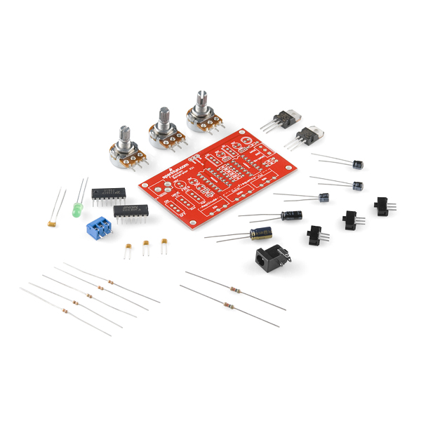
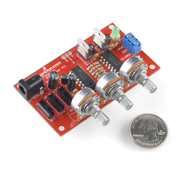
Description****: Nuxie and SparkFun worked together to rehash Nuxie's Function Generator Kit. This kit is based around the XR-2206 monolithic function generator IC, and can produce sine, triangle, and 5V square waves with frequencies ranging from 15Hz to over 500kHz.
A selector switch allows you to pick either a sine or triangle wave to be output to the 'WAVE' pin. The amplitude of this wave can be adjusted from about 1V up to either 7V (triangle) or 5V (sine). A square wave is also emitted by the XR-2206, and run a couple times through an inverter to even the wave out. This wave will have a maximum of 5V, so it can be interfaced with a microcontroller or other TTL-level devices.
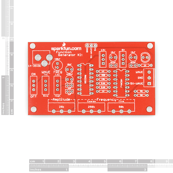
There are two selectable frequency ranges as well. When the 'FREQ' switch is set to Low, the frequency can be adjusted from 15Hz to 4.5kHz. In the High position, the frequency can go from 3kHz to about 650kHz. Two pots are used to adjust the frequency, providing both coarse and fine adjustments. The XR-2206 can emit frequencies from 0.01Hz up to 1MHz, if you need a frequency that this kit doesn't provide, we've broken out a couple extra resistors (R8, and R9), to give you the ability to customize your kit.
The XR-2206 requires a relatively high voltage for normal operation, this kit has it running at 12V. This means you'll need at least ~14VDC (no greater than 35V though!) to get the kit running at the optimal 12V. If you just want to use the 5V square wave output though, you could probably cheat and use a 9V wall adapter; we've used this in a few tests, and it hasn't caused us any problems.
Assembly is straight-forward and can be done with a simple multimeter for testing resistor and potentiometer values. The board is labeled clearly and should be good for beginners.
Lastly, if you'd like a quick and easy display of the frequency. This kit can be mated directly with our Frequency Counter Kit!
Replaces:DEV-09002
- Schematic
- Eagle Files
- Datasheet (XR-2206)
- Kit Review
Comments
Looking for answers to technical questions?
We welcome your comments and suggestions below. However, if you are looking for solutions to technical questions please see our Technical Assistance page.
Customer Reviews
No reviews yet.


Most excellent. The frequency ranges are approximate, due to tolerances on the resistors and capacitors, but what do you expect for the price? It would be nice to have standoffs either included or at least shown as optional accessories down below. An enclosure would be really cool, too, but then the switches would have to be relocated to provide access.
This is just what I've been waiting for; a XR-2206 function generator version with the SFE logo on the PCB. And it looks like there no feet for the PCB too (which is great for that "Spark Fun" effect on a crowded bench).
Of course, if I didn't have to have the SFE red PCB and logo, I'd probably go with something like the FG-500K kit, which comes with an enclosure, knobs, binding posts for connections, and costs $1 less (http://www.allspectrum.com/store/product_info.php?products_id=569).
Ok. I order this and 2 of the caps are missing. So you send me a new one and same thing. WHY?
My finger has gone numb from clicking on the tracking number link for an oscilloscope. Today I hope! Once it arrives I was thinking of harassing various
components I have laying around. I was thinking of trying some "curve tracing"
experiments. Does anyone know if I could use a function generator like this one
to trace output curves for diodes and possibly mosfet packages? If my goal sounds
a little vague, it's because I have little training in electronics but I know I'm a
visual learner and think this would be a good way to grock how components really
work.
Just put this together and used it to test out the $40 oscilloscope I got off ebay. Fortunately both worked great! Now to get a frequency counter...
It seems they will be discontinuing the XR-2206.
http://www.exar.com/Files/ChangeNotifications/PDN_11-0112-01-1033.pdf
And the MAX038 was discontinued in 2006.
DDS seems complicated.
What's a person to do?
I'm looking for a short cut to create a simple Wiegand Signal Generator and thought this kit might be a good starting point as it already gives the pulse at 0 to 5V.
So basically want a simple module to produce me a square wave pulse at intervals that match the Wiegand protocol - pulse width (Tpw) range 20 μs to 100 μs & interval width (Tpi) range 200 μs to 20 ms.
So instead of fiddling with potentiometers, I wondered would anyone know what resistor values I should replace them with. Also is there any clever way to split the signal for my Data 0 and Data 1 lines.
And if there is any other components settings to build this interface please let me know - e.g do I need to have a start and stop delay, if so what is needed to do this.
This kind of Wiegand Generator?
http://books.google.ca/books?id=iwEAAAAAMBAJ&pg=PA102&lpg=PA102&dq=Wiegand+Signal+Generator&source=bl&ots=03FtFgzarN&sig=yyG2pBpoHWvLAHZni_BmgQKR3_A&hl=en&ei=kfnYTY-ME4O5tweHw5XpDg&sa=X&oi=book_result&ct=result&resnum=3&ved=0CEwQ6AEwAg#v=onepage&q=Wiegand%20Signal%20Generator&f=false
http://en.wikipedia.org/wiki/Wiegand_interface
Answered my own question, yup.
i just received the kit and there was no data sheet, or assy instructions. just a bunch of components in a bag with a pcb. any help on where to get the info i need to get started would be great.
ah ha! I took a closer look at the PCB and that was all the instruction i needed! Everything is labeled in its place on the board. Well done.
Everything you need should be on the product page. Follow this link:
http://blog.littlebirdelectronics.com/kit-review-sparkfun-function-generator
not too experienced with electronics, but very interested in this kit! I could be mis-understanding the power supply requirements, but it seems as though you don't carry a good power supply for this, namely 24VDC one....am I mistaken? either way, what should I be looking for in a power supply? and also, will I need a separate power supply to mate the frequency counter with this??? thanks!
"If you just want to use the 5V square wave output though, you could probably cheat and use a 9V wall adapter;"
LOL
If you just want a square wave you can have it using a 555 and a few components for a fraction of the cost of this kit.
And you can also output pwm with it.
This is an excellent kit and alot of fun to build. I coupled this with a BNC jack and the frequency counter kit and now have a pretty handy trouble shooting tool. Need some sort of armored case enclosure for it though...
This function generator kit really works, is easy to assemble, and ideal for soldering practice as it can be used as a working piece of equipment for many years to come. Read more about it on my blog at: http://wp.me/pQmjR-1dk
Just a note: using the 12 volt 600 mA wall adapter below, the max voltage out (peak to peak, sine wave) is approximately 4.7 V, over most of the frequency range but the voltage drops nearing the top of the range. I'm getting about 31 Hz to 700 kHz. Does anyone have some numbers for a higher voltage supply?
Wondering why the Eagle Files archive doesn't include the .sch and .brd files?
Sorry about that, I just added the brd and sch files.
so, what would I need to do to produce lower freq's? I see mention of R8 and R9. I'd like lower frequencies, like 1HZ. Thanks! :)
Truly amazing! I STILL have a few of these hanging around from college... and that was 1985 /sigh/ The data sheet has a copywrite date of 1972!! You can drive small galvo's with these and put on a great laser show.. anybody?? anybody??