XMOS XS1-L1-64 Development Board
Replacement: None. It's time for this product to step aside and make room in the catalog for even more cool stuff. This page is for reference only.
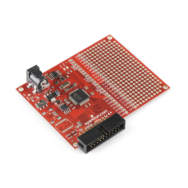
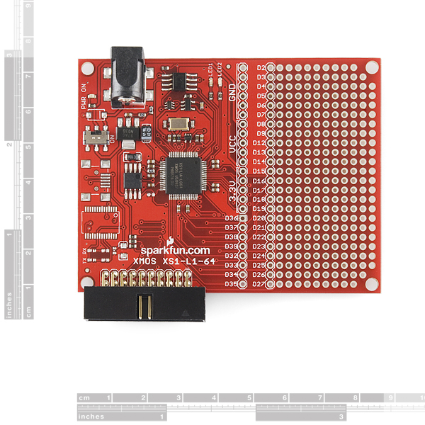
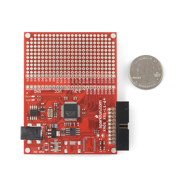
This is a development board for the impressively powerful XS1-L1, multi-threaded processor made by XMOS. The XMOS development board includes a XS1-L1-64 processor in a 64LQFP package.
L1-64 Features:
- Event driven processing at 400MIPS
- 64 kBytes of SRAM
- 8 threads
- 36 user I/O pins
- 8 kBytes of OTP memory for application boot code and security keys
A typical power consumption of 450µW/MHz
SparkFun's development board for this processor provides an XTAG header for either loading your code onto the external SPI flash or running your code as an XCore application. Thirty two user I/O pins are broken out for your prototyping needs. The board comes with the SPI flash already programmed with some simple example code.
The XS1-L1 is easy to use. The processor can be programmed using the XMOS Design Tools. A design tools supported USB to XTAG converter is needed to load your code onto the XS1. Our development platform can be programmed in the XMOS Development Environment. The SFE development platform can be programmed either by creating a project that uses the XC-5 Development Platform or by using the SFE.xn file found in the example code. Note that the XC-5.xn selects a 20MHz external oscillator. To have all timing I/O be properly scaled, you must change the oscillator frequency in the .xn file to 13MHz.
Note: This revision does away with the UART section of the board, which never really worked in the last revision.
Community:
Replaces:DEV-09428
- Board: 2.5x3.3"
Comments
Looking for answers to technical questions?
We welcome your comments and suggestions below. However, if you are looking for solutions to technical questions please see our Technical Assistance page.
Customer Reviews
No reviews yet.


Is there a bill of materials available for the schematic?
Can you specify the crystal information. I know its a 13 Mhz crystal but i would love to change it to a 20Mhz since its more common. Also its easier to obtain.
Like crystal datasheet or at least Package Size and Pinout...
Hey Sparkfun any chance on making a smaller version somewhat a clone of the XK-1 ? I would love to buy it... I just dont want to buy the entire $100 kit everytime and large boards like this make creating something small a hassle.
Making PCBs just waste my time and effort for finding and buying RARE or expensive parts in singles :)
Thanks for any input!
What's the size of the SPI flash?
Schematic Shows "AT25FS010" which is 1Mbit aka 128KB
1,048,576 bits / 8 (bits per byte) = 131072 Bytes / 1024 Bytes per KB = 128KB
I just found out theres no real reason to use more than 4 threads on this guy. Each thread runs at 100Mips until you reach 400Mips after which each thread will slow down to give you a total of 400Mips. So when all 8 threads are active you will have 50Mips*8 = 400Mips... Basically your performance maxes out at 4 threads.
I know its kind of late but even if you max out on 8 threads @ 50MIPS a thread. Thats still like having 8 MCUs running at 50MIPS. Way better than a PIC/AVR even some ARMS.
Also they can communicate with each other. And you can also link more together. So i think if you want to go crazy get 2 and link them so you can run 8 total threads at 100mips...
Ill be ordering this in 2-3 weeks and plan to go crazy...
Too bad it requires another thing for programming, which makes this nearly 99 bucks total to start up. :-( If it only would be like other solutions like the Arduino, FEZ Panda and Netduino: one box solution.
To know a little bit what happened with the old version this link can help you
http://www.xmos.com/discuss/viewtopic.php?f=3&t=590&sid=05bbd2b1f486f0a801be31b2e403a504&start=20
"Note that the XC-5.xn selects a 20MHz external oscillator. To have all timing I/O be properly scaled, you must change the oscillator frequency in the .xn file to 13MHz." To ask the obvious question, why not just use a 20MHz crystal? Why throw away 35% of the potential performance of this chip?
My mistake; I see that the operating speed of the chip depends on how the PLL is programmed, and hence a 13MHz oscillator can be used to run the system at the same speed as a 20MHz oscillator.
Why didn't the FT232 work on the old board? Isn't it the same circuit SparkFun always uses? I'd rather pay the extra money to have a working TTL USB interface.
How does removing a feature save hassle? Also you should update the description: "SparkFun's development board for this processor provides an FT232 to support a UART over USB"
The UART section never functioned properly. It is now removed so traces don't need to be cut. The price is lower to reflect this.