Danger Shield (Old-School)
Replacement: DEV-10570. The new version of this board uses a different temperature sensor and also replaces the knock sensor with a capacitive touch pad. This page is for reference only.
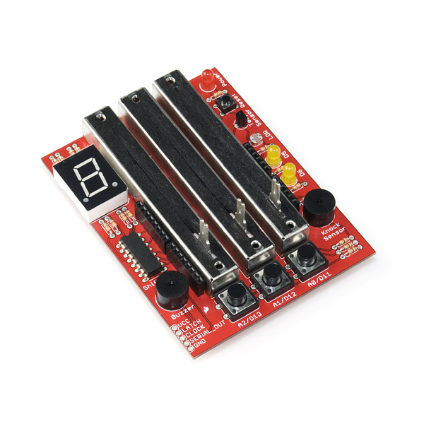
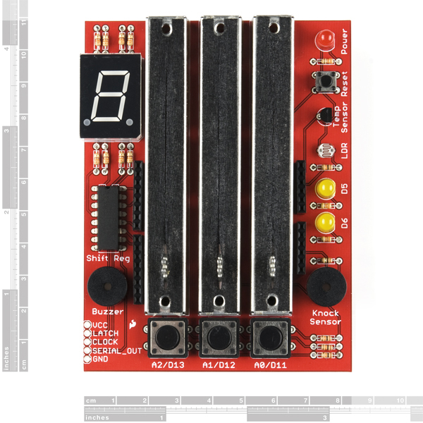
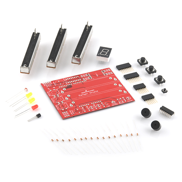
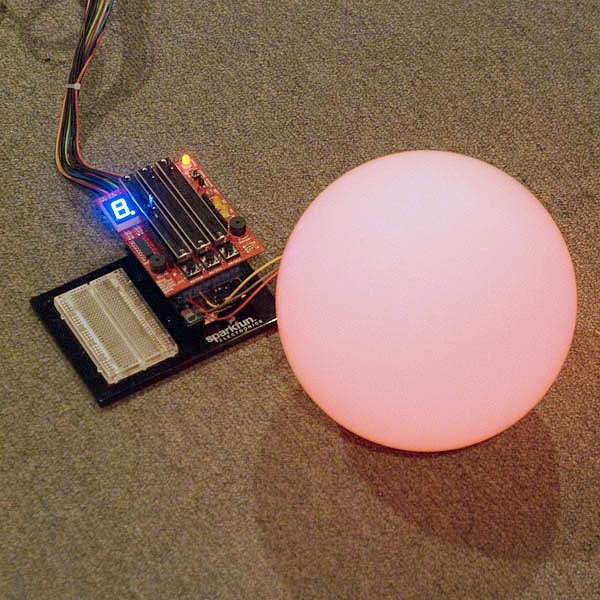
The Danger Shield mounts on top of your Arduino or Arduino Pro and equips it with a variety of fun and useful inputs and outputs. The Danger Shield has so much potential; we can't wait to see what you're able to do with it! The shield's features include:
- Three linear slide potentiometers connected to the Arduino's analog pins 0 through 2.
- Red and yellow LEDs connected to digital pins 5 and 6 - PWM pins - so you can easily vary their brightness.
- Three momentary push buttons connected up to the Arduino's digital pins 10 through 12. Those lines will go low when the buttons are pressed.
- A photocell and a temperature sensor, both with analog outputs, are connected to the analog pins 3 and 4, respectively.
- An 8-bit shift register set up to control a blue 7-segment LED.
Two buzzers - one is used, as you'd expect, as a speaker, the other is connected to analog pin 5 and can be used as a knock sensor.
This new version uses a different temperature sensor. This product comes as a kit of parts, which you'll have to solder into the included PCB. All parts are through-hole so it should go together relatively easily; but always check your component orientation before soldering!
**Replaces: **DEV-09597
- 1x PCB Danger Shield Kit
- 3x Slide Potentiometers - 10K
- 1x 7-Segment LED - Blue
- 1x 8-bit Shift Register - 74HC595
- 1x Temperature Sensor - TMP36
- 1x Miniature Photocell
- 2x Buzzers
- 1x Basic LED - Red
- 2x Basic LEDs - Yellow
- 1x Mini Push Button
- 3x Momentary Push Buttons - 12mm Square
- 11x Resistors - 330 Ohm
- 4x Resistors - 10K Ohm
- 1x Resistor 1M Ohm 1/6W
- 2x 8-pin Arduino Stackable Headers
- 2x 6-pin Arduino Stackable Headers
Comments
Looking for answers to technical questions?
We welcome your comments and suggestions below. However, if you are looking for solutions to technical questions please see our Technical Assistance page.
Customer Reviews
No reviews yet.

do the sliding pots work with product http://www.sparkfun.com/products/10761
I put this together yesterday, just getting into it hoping to learn. When I power it up, the power light turns on for just a second, and then goes off. I checked that I placed everything correctly and that the solder joints are secure. Any ideas for me on how to trouble shoot this. thanks
Just finshed assmebling my board and the test code ran ok with one exception. The period was lighting up on the 7 segment led when the middle led should have been. I had to swap the left most two bits in each array element to get everything to work. Is there a problem with mine or did they use a different 7 seg led that is possible wired different? I should mention that my Danger shield came with a 7 segment BLUE led if that helps.
Just got the kit and I am not sure in which direction I have to solder the buzzer/knock sensor? They each have a + and - but I cannot find any hint how to put them on the board.
This one caught me too. You'll notice that one of the holes on the board is round, and one is square. The square one is positive, the round one negative.
On the component, the positive lead should be labelled; also, the negative lead is shorter.
Thanks, got it working :)
Ground is the left pin respective to the small text.
HI,<br />
the pin is not compatible with the "original" dangershield<br />
http://www.flickr.com/photos/hoeken/2421984894/<br />
Infact the momentary push button are connected to d2, d4 and d7.
A nice build, but the execution has a few issues.
The magnetic buzzer can't really be used as a knock sensor, and the 6.5mm pin spacing is really weird and I can't find a piezo replacement--pin spacings are pretty much all 5mm or 7.5 mm in this size.
Also, the surface finish on this is really pretty, but doesn't solder well. I would up using paste flux to get the solder to flow into the holes. It doesn't help that the itty bitty resistors have very thin (26 or 28ga?) leads, and the holes in the PCB are about 5x bigger than the leads.
So will those of us who bought the botched version get a free TMP36 and a gentle pat on the bum? ;)