MPR121 Capacitive Touch Keypad
Replacement:SEN-12017. We've updated the package and a few traces on the new rev of this capacitive keypad, go check it out! This page is for reference only.
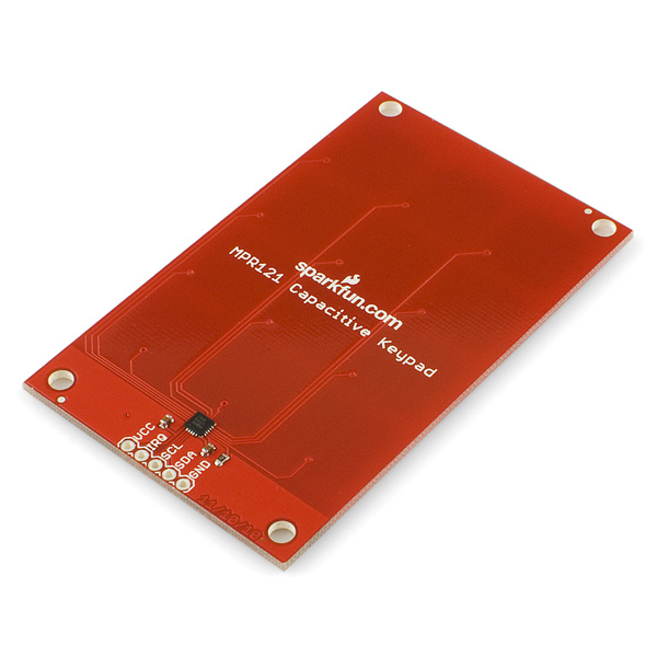
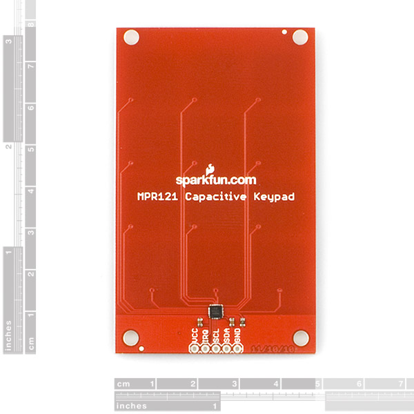
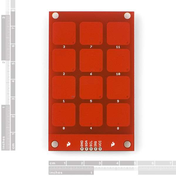
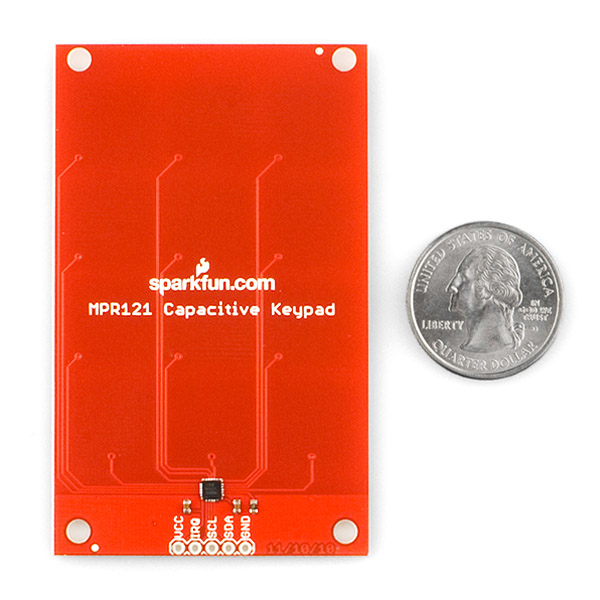
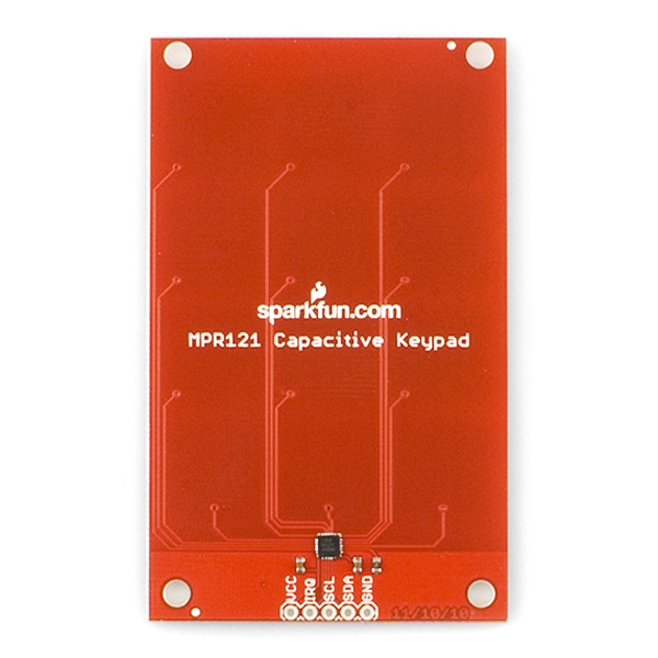
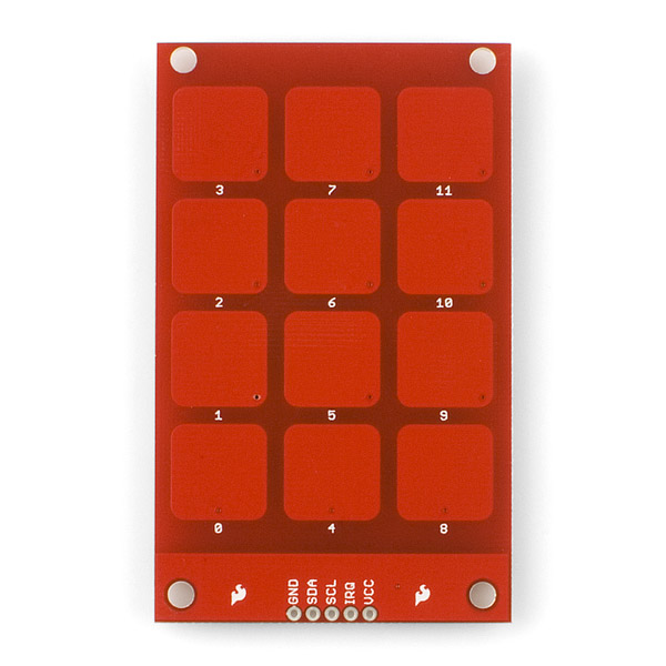
The MPR121 capacitive keypad uses the MPR121 and 12 touch sensitive pads to give you a simple 'keypad' with an I2C output. The board also has four mounting holes allowing it to be used as an input system in place of traditional buttons. Check the example code below for an easy way to read the keypad.
Note: This keypad outputs 3.3V logic. If you are using a board which only accepts 5V logic, you will run into a problem. You will want to use a logic level converter, or a board which accepts 3.3V logic.
MPR121 Capacitive Touch Keypad Product Help and Resources
Core Skill: Soldering
This skill defines how difficult the soldering is on a particular product. It might be a couple simple solder joints, or require special reflow tools.
Skill Level: Noob - Some basic soldering is required, but it is limited to a just a few pins, basic through-hole soldering, and couple (if any) polarized components. A basic soldering iron is all you should need.
See all skill levels
Core Skill: Programming
If a board needs code or communicates somehow, you're going to need to know how to program or interface with it. The programming skill is all about communication and code.
Skill Level: Competent - The toolchain for programming is a bit more complex and will examples may not be explicitly provided for you. You will be required to have a fundamental knowledge of programming and be required to provide your own code. You may need to modify existing libraries or code to work with your specific hardware. Sensor and hardware interfaces will be SPI or I2C.
See all skill levels
Core Skill: Electrical Prototyping
If it requires power, you need to know how much, what all the pins do, and how to hook it up. You may need to reference datasheets, schematics, and know the ins and outs of electronics.
Skill Level: Noob - You don't need to reference a datasheet, but you will need to know basic power requirements.
See all skill levels
Comments
Looking for answers to technical questions?
We welcome your comments and suggestions below. However, if you are looking for solutions to technical questions please see our Technical Assistance page.
Customer Reviews
No reviews yet.

I am trying to interface the MPR121 with 5v 8051 micro controller. I have also purchased the logic level converter. Should i used pull up resistors for the IRQ pin even if i use a logic level converter ?
I connected the I2C lines and the Interrupt to 10k pullup resistors(3.3V) and I am using the sample code from bildr. But, whenever I touch one of the pads, the interrupt goes low but when I try to request bytes, the chip freezes and I have to cycle the power. I was wondering if there was a fix for this problem. BTW I am using an arduino and the logic level converter.
I have a board that yields 5v logic. What that part number for the 3.3v logic board that I can use for my micro?
I have a Arduino UNO and Mega. Do I need a logic borad for this?
It's a bit late for this now, but here it is, just for reference.
Yes, you would need a logic level converter board. The keypad runs on 3.3V, however both of those Arduinos run on 5V, so you would need the converter to step-up the logic coming out of the board.
Bit confused about this... It looks like the soldermask remains on the button pads... is it just thin enough for it to work? In the video Rob uses regular copper strips, uninsulated...
Corner. Self painted into ... check!
Recommendation for this and similar boards: when given the option of allowing the user to configure the device via pin settings, please allow for it. By using a pullup, pulldown or jumper on ADDR you would have allowed us to easily change the I2C address without an x-acto knife. This board, not so flexible.
has anyone seen this? Actually this is what we all need, dont you think so?
touchpad
This is a 4x3 with an output just like a normal keypad.
i hope that someone from sparkfun will see that and provide it to us for sale.
thanks to all sparkfun team in advance.
Does anyone have a diagram for connecting this thing to a 5V Arduino using Sparkfun's logic level converter? Thank you!
See the Touch Shield in the related items below.
Awful lot of highlighted ????s in that data sheet...
Would be able to interface directly with Arduino Uno using the 3.3V into VCC or would it still require a logic level converter?
I connected it directly to my Uno as you described and it works perfectly.
http://mbed.org/users/4180_1/notebook/mpr121-i2c-capacitive-touch-sensor/ has a code example for mbed
ASCII version ... LOL.
The schematic says the device address is 5A, but according to the datasheet, if ADDR is ground, the address is 5B.
"The device has a configurable I2C address by connecting the ADDR pin to the VSS, VDD, SDA or SCL lines, the resulting I2C addresses are 0x5A, 0x5B, 0x5C and 0x5D respectively."
The datasheet refers to ground as VSS, so indeed, the address is 0x5A. If ADDR was tied to VDD (the supply), then the address would be 0x5B.
Any idea if this would work through glass? I really want to add a keypad based entry to my wife's car, and a capacitive keypad would allow me to keep the electronics inside the card.
Undoubtedly yes. The iPhone, for example, uses capacitive touch through glass.
It could work, but it would probably require changing the sensitivity of the buttons. My first guess would be changing the thresholds in "Section C" of the example code. I do not know for sure though.
Why wouldn't you be able to use this with 5V parts? 3.3V is usually sufficient enough to register as logic HIGH on 5V parts.
Just make sure your i2C pull-ups are to a 3.3V rail, not the 5V one. If the i2C pins on the part have clamping diodes, you could even pull-up to 5V if you wanted.
If you're really having logic level issues, just use an N-channel enhancement MOSFET on the SDA line (tie the gate to 3.3V, source to the 3.3V part, the drain to the 5V part).
Obviously you won't need any logic conversion for the clock line.
Of course, make sure you don't actually power the part on a 5V rail :)
Next version put the option for an regulator and and an optional shifter. :) Please.
me too. what would be really nice would be v2 with holes in the middle and indicator leds.
I've been waiting for something like this for forever. You should make one of these with an onboard regulator.
it's a simple breakout , no regulator so yeah, you'll fry the MPR121 (take a look at the DS)...