SparkFun Breadboard Power Supply Stick - 3.3V/1.8V
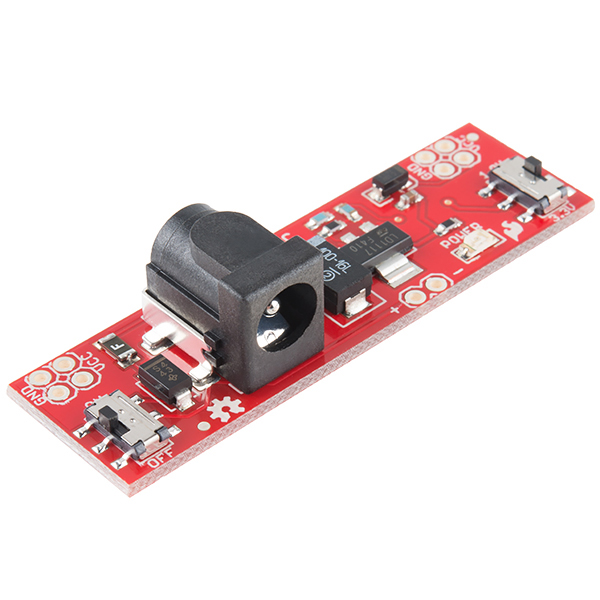
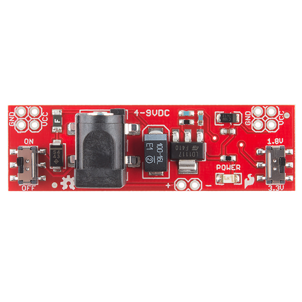
This is a very simple board that takes a 4-9V input voltage and outputs a selectable 1.8V or 3.3V regulated voltage. All headers are 0.1" pitch for simple insertion into a breadboard.
Input power can be supplied to either the DC barrel jack or the two pin header labeled + and -. Output power is supplied to the pins labeled GND and VCC. Board has both an On/Off switch and a voltage select switch (3.3V/1.8V).
The two sets of four GND and VCC pins are spaced such that when connected to our Basic Breadboard both power busses will be powered.
Note: Headers are not supplied. You will need to supply your own headers to connect this board to a breadboard. Check below for some breakaway header strips.
- 4-9V input voltage via barrel jack or 2-pin header
- 3.3V or 1.8V regulated output voltage
- 800mA Operating Current
- ON/OFF switch
- Output voltage select switch
- Power status LED
- PTC fuse protected power
- 5.5x2.1mm center positive barrel jack
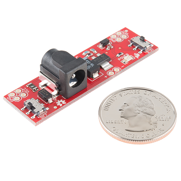
- 2.15x0.65"
- [Schematic](https://cdn.sparkfun.com/datasheets/Prototyping/Breadboard Power Supply - 3.3-1.8SMD_V14.pdf)
- [Eagle Files](https://cdn.sparkfun.com/datasheets/Prototyping/Breadboard Power Supply - 3.3-1.8SMD_V14.zip)
- Unregulated Power Supply Tutorial
- GitHub (Design Files)
SparkFun Breadboard Power Supply Stick - 3.3V/1.8V Product Help and Resources
How to Use a Breadboard
May 14, 2013
Welcome to the wonderful world of breadboards. Here we will learn what a breadboard is and how to use one to build your very first circuit.
Core Skill: Soldering
This skill defines how difficult the soldering is on a particular product. It might be a couple simple solder joints, or require special reflow tools.
Skill Level: Noob - Some basic soldering is required, but it is limited to a just a few pins, basic through-hole soldering, and couple (if any) polarized components. A basic soldering iron is all you should need.
See all skill levels
Core Skill: Electrical Prototyping
If it requires power, you need to know how much, what all the pins do, and how to hook it up. You may need to reference datasheets, schematics, and know the ins and outs of electronics.
Skill Level: Rookie - You may be required to know a bit more about the component, such as orientation, or how to hook it up, in addition to power requirements. You will need to understand polarized components.
See all skill levels
Comments
Looking for answers to technical questions?
We welcome your comments and suggestions below. However, if you are looking for solutions to technical questions please see our Technical Assistance page.
Customer Reviews
No reviews yet.


This might seem an odd question, but at 4-9V input... Has anyone considered making aversion of this board with a micro-usb input connector? I can't speak for everyone, but between phones and tablets, i have an excess of micro-usb cables laying around, and im sure I can't be the only one with nothing to do with them.
Good and bad with this thing... The good, it works.. The bad, it takes some slight header bending for it to fit even the sparkfun solderable protoboards (These: https://www.sparkfun.com/products/12070). The other issue seems to be that the schematic is definately out of date... it's missing one of the diodes that is on the board (That appears to be for reverse polarity on the output?)...
Any specs on how much current or power this can supply? Voltage alone is only half the equation. ;-)
The regulator on board is rated to a max of 800mA.
Need to be careful here - the 800mA Operating Current listed is misleading if not put into context.
Only the regulator IC (LD1117) is rated at 800mA. The total amount of current this board can supply is dependent on several factors, most importantly, the total power required (Watts, based on Vin, Vout, Iout), and the ambient temperature.