Dev Platform for LPC2148 - Uberboard
Replacement:DEV-09735. This has been replaced with an updated version. This new version of the board has a MMA7361 instead of the MMA7260. This page is for reference only.
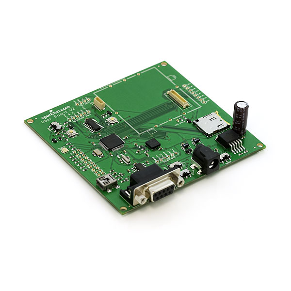
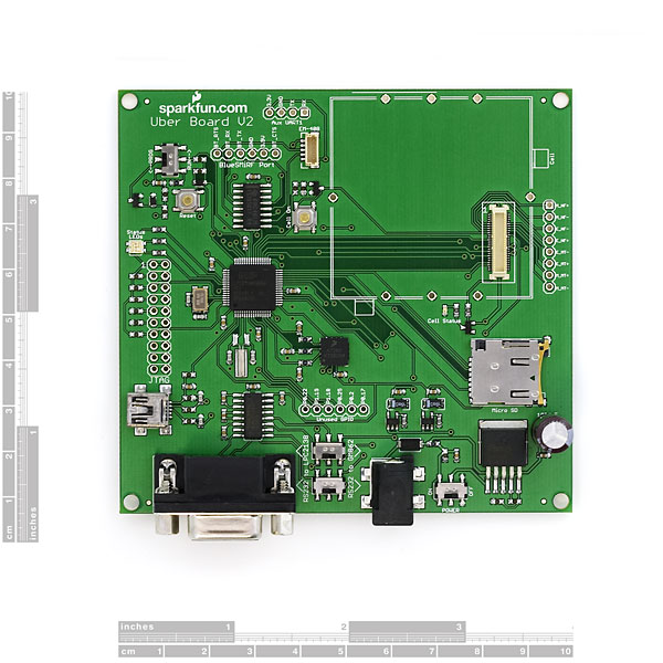
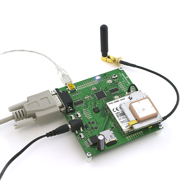
The Über****board is back. This is a fairly large board with cellular, GPS, accelerometer, data logging, Bluetooth®, and USB development. This board combines the power of the Phillips ARM core along with empty sockets for many of the powerful components from SparkFun.
empty sockets for peripheral components. These extra components must be ordered separately.
- LPC2148 - 60MIPs ARM processor with 512k flash
- 12MHz crystal for USB
- Limited USB support
- 32.768kHz RTC crystal
- Socket for EM408 SiRF III GPS receiver
- Socket for GM862 global cellular modem
- Socket for micro SD card (up to 2GB)
- Socket for BlueSMiRF short range RF modem
- Triple Axis Accelerometer MMA7260QT
- Tri-color LED for color mixed status indicator
- JTAG port for debugging
RS232 for debugging and external communication
Using the LPC2148 and the GCC free tool chain, you can setup all sorts of applications! From vehicle tracking, package tracking, person tracking, shock/drop detection, data logging, cellular email notifications, wireless data capture - you name it, the Uber board has it covered.
This product comes with
-
Source Code:
- Flash Magic
Comments
Looking for answers to technical questions?
We welcome your comments and suggestions below. However, if you are looking for solutions to technical questions please see our Technical Assistance page.
Customer Reviews
No reviews yet.


I would realy like some bentchmark tests and usb com port code examples. Full speed usb for high speed data logging.
Please, could someone tell me how to use the bluetooth from uberboard?
because i just can turn it on but and nothing else. How to programer it? Does someone have any code about it?
please, send me an e-mail: jhcbj@hotmail.com
P.S.: sorry for the wrong english
Please contact techsupport@sparkfun.com. Thanks.
Hi - is the clock fixed at one frequency or can it be changed (eg pluggable crystals) and I so what's the highest speed the whole board can run at - or is it only limited by the MCU?
I've been able to change my clock freq from 48Mhz to 60Mhz. I think the fastest it can go is 60Mhz. Hope that helps.
I was wondering if it matter, but on the schematics it says the ARM is LPC213X but the header files and the title of the ARM on the product description is LPC214X. I kind of think it needs to be updated/change since it is not accurate.
--- HOW TO USE THE BOOTLOADER INCLUDED ON YOUR BOARD ---
Make sure you add the following to the Makefile:
change
build: elf hex lss sym
to
build: elf hex lss sym FW.SFE
--- insert this ---
FW.SFE: main.elf
@echo
@echo $(MSG_FLASH) $@
$(OBJCOPY) -O binary $< $@
--- after this block ---
Create final output file (.bin) from ELF output file.
%.bin: %.elf
@echo
@echo $(MSG_FLASH) $@
$(OBJCOPY) -O $(FORMAT) $< $@
and in the common folder change the following text in the file: LPC2138-ROM.ld
change
ROM (rx) : ORIGIN = 0x00000000, LENGTH = 512k
to
ROM (rx) : ORIGIN = 0x00010000, LENGTH = 380k
Otherwise it will won't write the file. Since the bootloader is sitting at 0x00000000.
I burned a few hours and brain cells on these issues. So, I hope it helps you!
There is a bug in the demo source code for what I assume to be some of these boards?
It causes the enable pin of the EM408 to no longer work. It scared me a little since I thought I burned a pin.
I compiled and loaded the demo from the V2_4.zip and it no longer allowed me to use GPS. I found the bug after tracing the fact that the Schematics is actually wrong for my board. The Enable pin off the GPS actually goes to Pin 1 of the ARM Proc.
In the code you need to change the 0x00800000 to 0x00200000 when you find an EM_408 power note. It is in 4 spots at least (init and stuff). It is P0.21 not P0.23(pin 53).
Hi,
What development environment will be needed for writing code for this board?? Is there an open source IDE available??
How will we program(flash our code) this board and what tools and programmer will be required(JTAG , Serial)??
Please suggest.
Hi there,
Yes, you should be able to use everything associated with the GM862-GPS module.
Pete
Can you use the GM862-GPS module with this board and use all of the GPS functions included in the GM862-GPS module?