SparkFun USB LiPoly Charger - Single Cell
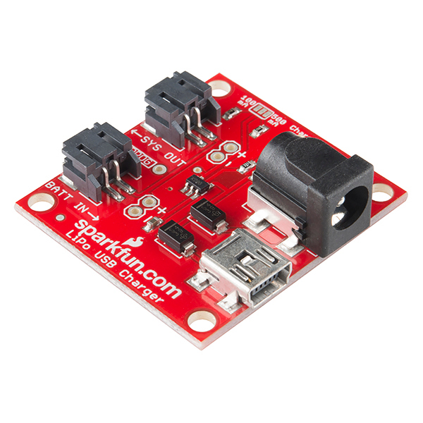
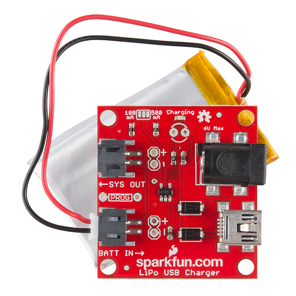
If you need to charge LiPo batteries, this simple charger will do just that, and do it fast! The SparkFun USB LiPo Charger is a basic charging circuit that allows you to charge 3.7V LiPo cells at a rate of 500mA or 100mA. It is designed to charge single-cell Li-Ion or Li-Polymer batteries.
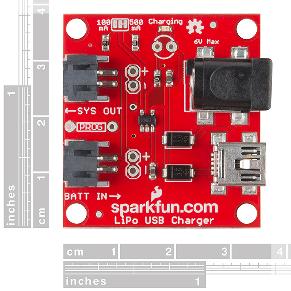
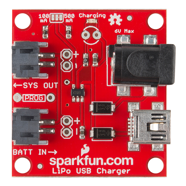
The board incorporates a charging circuit, status LED, selectable solder jumper for 500mA or 100mA charging current, external LED footprint, USB input, two pre-installed JST connectors for SYS OUT and BATT IN, and (back by popular demand) a barrel jack connector.
There is also a 'SYS OUT' with a pre-installed JST connector which allows you to connect the charging circuit directly to your project so you don't need to disconnect the charger each time you want to use it.
- Schematic
- Eagle Files
- Hookup Guide
- Datasheet (MCP73831T)
- GitHub (Design Files)
SparkFun USB LiPoly Charger - Single Cell Product Help and Resources
LiPo USB Charger Hookup Guide
May 1, 2014
How to charge your LiPo batteries with the USB LiPo charger. Plus how to modify your charger to set the charge current.
1 of 1 found this helpful:
Power Supply
While the chip can take up to 6V for the maximum voltage, it can only take 1500mA for the max current. If you use the 6V 2A power supply as the power supply, then you are very likely to burn the chip out on the board. If you need a power supply with a barrel jack, then we recommend the 5V 2A supply.
Core Skill: Electrical Prototyping
If it requires power, you need to know how much, what all the pins do, and how to hook it up. You may need to reference datasheets, schematics, and know the ins and outs of electronics.
Skill Level: Rookie - You may be required to know a bit more about the component, such as orientation, or how to hook it up, in addition to power requirements. You will need to understand polarized components.
See all skill levels
Comments
Looking for answers to technical questions?
We welcome your comments and suggestions below. However, if you are looking for solutions to technical questions please see our Technical Assistance page.
Customer Reviews
4.4 out of 5
Based on 8 ratings:
1 of 1 found this helpful:
Works well.
I have this integrated into a prototype. I have done dozens and dozens of USB insertions/removals. No problems.
2 of 2 found this helpful:
Good idea but bad quality.
I tested it with the wall plug first and it worked as advertised so I installed it in my build. Once installed I wanted to charge it via USB and when I tried to plug it in all solder points came lose and the entire USB socket came off so I had no other choice but to use the wall plug. Too bad. I wanted to have both options but because of bad manufacturing I was left with one.
Those USB ports tend to be more resilient. I'm contacting you privately to discuss your issues. Thanks
0 of 3 found this helpful:
Expected wider input range
Completely my fault for not paying attention ... but all of the barrel jacks on my other "redboards" will accept 7-15 volts. If I would have read either the documentation or the "6V Max" etched on the board no problem .... smoked of course in a few seconds with a 12V wall wart. :(
Very good charger for LiPo;s
This charger is simple to use, and great for use with Sparkfun's LiPo batteries that I use to power the MicroBit.
USB LiPoly Charger-Single Cell
Highly recommended product:)
Great for embedded projects
I use this in a rechargeable light source in an escape room! The wired version has worked flawlessly. One of them that was hooked up to an inductive charger burnt out. This was possibly due to the inductive system and not the charger.

Does it possible to charge lipo battery while load is connected via this charger ?
Just simple question, but what is the output of the charger to the battery? Could it be used to power the GSM800L board? Not the shield, but the board.
is it possible to charge Coin Cell Battery - 24.5mm (Rechargeable CR2450) with this charger
Another idea to the D+ and D- lines for the USB connector: A USB passthrough, with the ability to turn off power from the USB connector - I want to pretend the power is only coming from the "battery", but I want to connect to the "Serial" port via USB data connection.
Can I buy 2 lipo batteries and 2 chargers and hook the sysout in series to get ~7.2V ?
Is it possible to connect the LiPo Fuel Gauge (https://www.sparkfun.com/products/10617) to this?
Breaking out the D+ and D- lines of the USB connector to solder points would be a nice feature on a board like this.
Yes a lot ! Why Sparkfun don't add this ?
I am wondering if anyone can provide some tips on the selectable solder jumper? I have the single-cell, 110mA batteries, part number PRT-00731. I'd like to connect the two on-board resistors in parallel to tenderly charge the batteries at 60mA. I am just wondering if there is a simple way to jump the traces without using solder. Maybe a miniature clip or something like that?
Both resistors in parallel would give around 600mA, not 60mA! I think you mean you want to put them in series, but I don't know if any micro grabbers that would reliably grab resistors to accomplish that without solder.
My suggestion is to replace the resistor with a 16k ohm resistor to get 62mA or an 18k resistor to get 56mA. You can get the surface mount resistor for pennies plus shipping at digikey, then you just need the soldering iron, solder, some braided solder wick, tweezers, and a head mounted magnifying glass.
I know that's not what you asked, but when you get to the point that you want to modify boards, you should really spend a few hours watching YouTube soldering videos, then jump in and see that it really isn't too hard. Trying to macgyver surface mount resistors just isn't going to turn out well without solder!
The easiest thing to do would be to use a knife to cut the small trace between the center pad and the 500mA pad. Then get a regular through hole resister and solder it into the "prog" space between the two JST connectors. Page 7 of the datasheet has a chart showing which resister to use to achieve a given output current. For 60 mA, you should use a 16k resister.
Did you ever find out a solution? I'm wondering this too.
Hi. I’m thinking of using it as a solar charger/batterypack.. Can I connect a 8v 310mA solarpanel via the 5v input? Thanks.
I tried attaching an external status LED to the two contacts provided just beneath the built-in LED, but my LED did not light up.
Is it possible that you can't have both the built-in LED and an external LED at the same time?
Has anyone successfully attached an external LED?
Any help would be greatly appreciated!
From the board, it looks like the battery in and system out are connected and just have different labels on them but could be used for either. Would somebody confirm that I'm not reading that wrong?
If the battery finished charging and i continue using the device, what's going on ? Will the battery always be discharging and charging again ? Can I use this for a 24/7 device which works on batteries only 2 hours per day and is plugged to power most of the time ? Is there an advised kind of battery for the case ? Thanks
Have 4 type's of lipo's 100mA, 240mA, 350mA and 850mA, can I use something like this Potentiometer variable resistor or this Rotary Wirewound Precision to do the job?
Hi, I am wondering what happens if my system is powered while I'm charging the battery. Will it work fine just like most recent computers ?
Could some body explain how the switching between the baterry and the usb power supply works ? I'm wondering ... ? Please. is the part POWER_JACKSMD a relay ? I need your help.
The datasheet for the MCP73831T says it charges at 4.20V, but I'm using it with the 3.7V LiPo battery you sell ( https://www.sparkfun.com/products/341 ) Should I expect problems?
No - the charging voltage for lithium batteries is generally 4.20-4.35V. Most lithium batteries have a median voltage of 3.7-3.8V, but they charge at voltages higher than median. If you look at the discharge specs for lithium batteries, you'll see that the voltage starts at 4.2 then goes down.
Is it possible obtain the same product but with a micro-B USB port instead of the (deprecated) mini-B USB port? Thanks
Hi All, The hookup guide says this about the jumper pads on the board... "As an advanced trick, you can short both pads to the center (connecting both resistors in parallel) to set the charge current to 60mA."
Can someone verify this is indeed true? 60mA? I'm a little skeptical because one is 100mA, the other is 500mA... 100 + 500 = 600... Logically, I would assume jumping both would be additive, but I am not an EE. I've blown up enough circuits to conclude that electrical engineering is more magic than logic.
The datasheet says Ireg=1000V/Rprog, and 100kohm || 2kohm ~= 1.667kohm, for a resultant Ireg of 600mA.
Also, can someone describe a way to definitively test the output with a scope or meter?
What sort of current can be drawn from the sys out jack as I would like to run a 1A 5v booster circuit from it
Can I use this to have the battery charge the USB device (like an iPhone or something)? Instead of the other way around?
No, sorry. That's am entirely different circuit, and charging iDevices requires authentication in most cases.
Just buy authentic, overpriced apple accessories to avoid a headache!
Is there a board like this that I can use on AA (NiMH) batteries? (with the sys out option)
Question:
What JST connector series is used?
Answer:
2-pin JST-PH connector - 2mm spacing between pins.
Buy Cables Here
Search - 2-Pin JST-PH
Hi. Which is the max output current supplied by SYS OUT?
Thanks
The charge current plus whatever the battery can supply. Note that the battery will only charge if you draw less than the charge current, otherwise the battery will discharge.
I want to charge at 100ma.
All I have to do is solder a small wire between the middle pad and the pad juxtaposed to the 100ma pad, correct?
Thanks, Doug
Even better, you don't need a wire! Just remove the solder connecting to the 2k resistor (500mA side) with solder wick, and add a blob to"jumper " the pads on the other, 100mA side!
Will this charge 18650 cells?
This will charge a 18650 battery IF it is 3.7V and a li-poly or li-po battery. It will charge at a rate of 500mAh. So if your battery is 5000mAh is will take 10 hours to charge. As noted above by IgnacioV, "the battery will only charge if you draw less than the charge current, otherwise the battery will discharge."
I'm trying to connect a Sanyo am-7d08 panel using the barrel jack it came with.
http://www.msc-ge.com/download/sanyo/glass/AM-7D08.pdf
I'm not sure if it would burn out the charger and also can the included USB jack charge a cell phone for example? Or is it just input?
What would be the best way to make/get one of these at higher voltages? The best option I'm thinking is resizing the circuit and putting it on a breadboard....I'd appreciate any ideas.
Will this board still power SYS OUT if the battery is disconnected but a wallwart or USB is plugged in?
It doesn't look like this charger has undervoltage protection, right?
On PRT-11231 it says it cannot pull more than 100mA from the USB connector without a chip negotiating with the host for more current (USB standards). Does this one have the same limitation? It doesn't have a chip to request higher current. Or does it just assume you're powering from a powersupply like a wall-wart that supplies 500mA-1A/5V?
this appears to be the same, but it really depends on the USB host. some will give the 500ma, or more, without negotiation, especially USB hubs.
this one makes me happy.
some phone and camera batteries have three contacts. can i still use this if im really careful?
what would you suggest?
thanks!
As long as the phone battery doesn't have some kind of protection circuit that forces it to use a "known" charger (don't know how common this is, if it even exists :D), I don't see any problems with using this. Can't stress this enough though, Li-Ion and Li-Poly are very dangerous, even if you know what you're doing.
Check below about the third pin.
3 wires means it's multi-cell (the 3rd wire is for load balancing). This is definitely not a load-balancing circuit.
Most camera and phone-batteries are single-cell (3.7 volt) and the third pin (often in the middle if I'm not mistaken) is for either 1-wire communication or internal temperature sensor.
What happens if the power source (from the barrel jack for example) cannot supply 100mA? Will the battery just take longer to charge? If, for example, I wanted to charge a Li-ion battery using an inductive charging technique that doesn't quite supply 100mA, could the battery still be charged with this product, or would something else work better?
Made a comment I can't delete. Moved it to PRT-10161 where it belonged. Issue with charging LED not going out, see other post. May or may not apply to this model.
It is not mentioned here, but you need a walwart of “A supply voltage of [VREG (typical) + 0.3V] to 6V is recommended”. (from Page 11 of the MCP73831T datasheet) There is a schottky diode in series with the barrel jack connector so, in this case, the voltage range for the walwart is [VREG(typical) +.5V] to 6.2V, (assuming Diode Vf = .2V).
VREG is 4.2V, and the exact part no for the lipo charger is MCP73831T-2ACI/OT