MEMs Barometric Pressure Sensor - SCP1000 Breakout
Replacement:SEN-09694. This is not a direct replacement but is a suitable substitute for most projects. This page is for reference only.
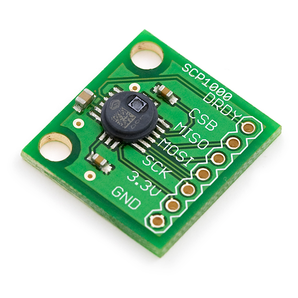
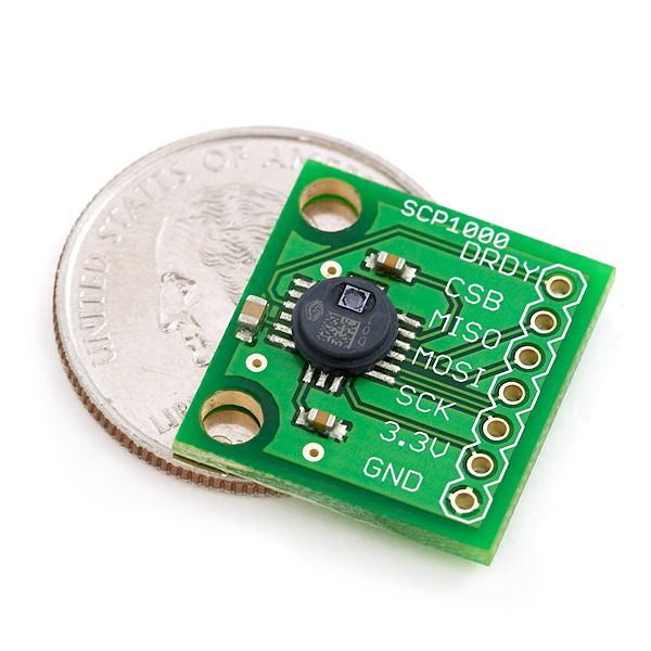
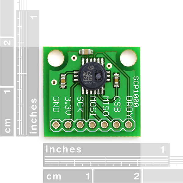
The SCP1000-D01 is a great IC - now you can play with it! This is a simple breakout board bringing the SPI interface pins to a 0.1" header.****Please note, we now stock the latest ASIC rev C (IC label 'D01').
The SCP1000 is the very first absolute pressure sensor on the market to use MEMS technology to grant 17-bit resolution. Under ideal conditions, this sensor can detect the pressure difference within a 9cm column of air.
VTI's SCP1000-D01 digital absolute pressure sensors are intended for barometric pressure measurement and altimeter applications for 30kPa to 120kPa and -20C to 70C measuring ranges. The pressure and temperature output data is calibrated and compensated internally and the communication between the SCP1000 and its host micro-controller is realized using an SPI interface. SCP1000 is comprised of a VTI's 3D-MEMS capacitive sensing element, a dedicated low power CMOS interface ASIC with on-chip calibration memory, 4 preset measuring modes and a LCP (Liquid Crystal Plastic) MID (Molded Interconnect Device) housing. The component is a surface mountable device incorporating a circular vertical wall for easy waterproof sealing.
Four user selectable measuring modes combine 17-bit resolution (9cm of air column) with low or ultra-low power consumption, or alternatively 15-bit resolution (18cm of air column) with high speed data read (9Hz) or less than 5uA and power consumption. For example, at Low Power mode, the SCP1000 has an overall resolution of 2 Pa (15cm of air column) and a power consumption of 3.5uA. This unit comes in a newly developed RoHS compliant plastic housing. Normal hot-air rework will destroy this sensor so we highly recommend this breakout board for prototyping.
Check out these really well done tutorials on bit-banging SPI with the FT232. Nice work Michael!
Note: If you plan on using this board in direct sunlight, we suggest purchasing the SCP1000 Gasket as shown below in the related items.
Comments
Looking for answers to technical questions?
We welcome your comments and suggestions below. However, if you are looking for solutions to technical questions please see our Technical Assistance page.
Customer Reviews
No reviews yet.


could you please send me example AVR code?
I am facing the same situation as signal7 and feel a quite disappointed...
Would it be possible to get the "Dimensional Drawing" suitable for the "red/old" version?
Thank you.
Issue with the latest rev: SFE designers have added a surface mount resistor on the edge of one of the mounting holes. I like that there are mounting holes (more of your breakouts need them!), but the placement of this resistor makes it so I can only use one mounting hole. Please fix and update the pictures of this board.
Further reading of the comments implies that I have an old board (and I just received it today). Red board with PD and TRIG. Not sure how that could happen, but my product doesn't match what's on this page.
Is it possible to destroy the sensing element in this unit by cooling it down too fast? E.g. by a drop of liquid butane (-35 �C) to verify one's thermometer code for negative temperatures? :-) The measurement membrane appears to be cracked, and the readings are for all purposes stuck at about 81 kPa (ignoring vertical movement by as much as 500 meters), while my location should read approx. 91 kPa of static pressure.
If so, then you have a sale on your hands, sparkfun ;o)
I bought the old (red) version of this device right before the new (green) one came out. In addition to all the pins that the new one has, the old one has two more pins labeled "PD" and "TRIG." What do I do with those?
"Trigger" and "power down", according to the datasheet.
I'd like the I2C version breakout board too. Any news on that?
No one answer MFMD question. Can I use this sensor for underwater depth measurement?
Or does someone recommend other sensor?
Can I use this sensor for underwater depth measurement?
I am trying to use this sensor for accurate altitude measurements. Sitting on my desk it wanders as much a 5 feet. Has anyone gotten stable measurements in the range of the 9 cm they advertise - or even close? I'm trying to figure out what I could be doing wrong. since .03 hPa is a foot, I need to get very stable reading out of this sensor.
Thx
I have created an interface on LabVIEW with Arduino here
Does anyone know of Arduino Code that works with this model? Everything I've seen seems to have been with the previous one (not the D01). I'm trying to get the Razor 9DOF IMU to read the data from the sensor over SPI (since the Razor has an Arduino bootloader), however I'm either getting constant values (no data is being received) or nothing at all. Any help would be greatly appreciated!
Thanks!
Don't try to share the SPI-bus with other stuff! Even though the CSB-line is inactive it will get confused and shut down, requiring hard reset (pulling the plug).
I got it to work together with a MicroMag, but with an SD-card, no, it would just die.
What is the future of this board? The VTI website lists the SCP1000 as an obsolete part.
Any suggestions of a suitable replacement?
An I2C version would be greatly appreciated - as others have said!
So... just making sense of this. If i were to make this into an altimeter... with a max altitude of 100mtrs, would this work? Is there any documentation I can view?
Any chance to see the D11 version (I2C) sold by SF ?
Add me to the I2C!
Id appreciate that too!
Shouldn't it be MEMS and not MEMs? Micro Electro-Mechanical Systems?
Works well in tri rotors. The key is to mount it far from propeller wash. Single rotors don't have any place isolated from propeller wash but tri rotors do. Use high speed sampling, heavy lowpass filtering, & a 1 second time base to get climb rate & absolute altitude.
this thing needs very clean power to deliver good results. and if you design your pcb for this breakout-board, connect the drdy pin to the cpu (and give it it's own regulator with good caps). polling the status-byte for new data already messes up heavily with the result, around 4 times the usual variance (var^2 to be exact).
computing the variance is a very good and easy way to see results of power filtering.
VTI has a good and heavily-commented example C program here.
It uses the SPI hardware on an ATMega16L, and is easily portable to other AVR devices. The reading/writing functions (especially for indirect read/write registers) would be useful for other devices as well.
Keep in mind that this code was written for the first revision of the SCP1000. With the current revision stocked by SparkFun, you can skip step 6, the low-noise configuration (although it doesn't hurt to leave it in).
-Adam
Code to use this with Arduino is here.
I copied this code and I have received following result:
Initialize High Speed Constant Reading Mode
PRESSURE [1073740710]
TEMP F [75]
PRESSURE [1073740717]
TEMP F [75]
PRESSURE [1073740718]
TEMP F [75]
The temperature agrees well but the pressure ?????
My board is a Ardunio Pro 328 3,3V 8 MHz and I have installed the IDE 0017. (Windows)
Do you have an explanation for this result ? and perhaps you know where the error could be.(Timing?)
Willy