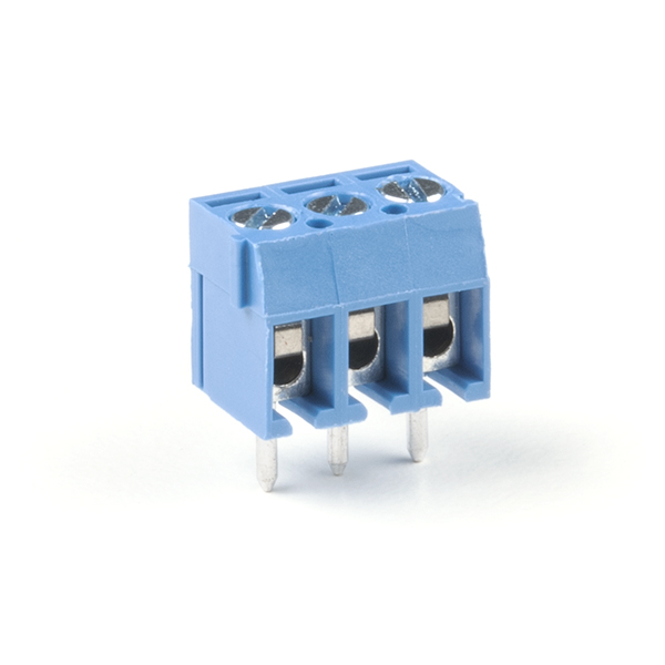
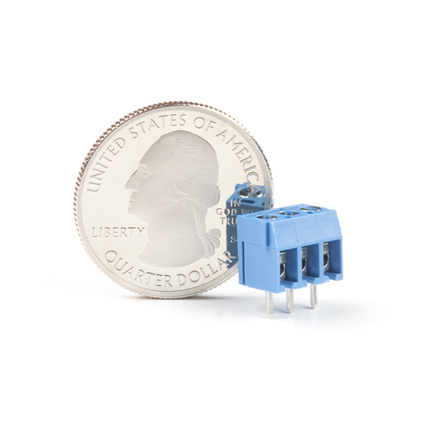
Screw Terminals 3.5mm Pitch (3-Pin)
Screw Terminals with 3.5mm pitch pins. Comes in 2, 3, or 4 positions and have the really cool feature of slide-locking together to form any size you need (4, 5, up to 20 without problems). Rated up to 125V @ 10A. Terminal can accept 16 to 26AWG wire. 3.5mm/138mil pin pitch will not fit standard 0.1" perf boards but this is the most common pitch screw terminal.
Screw Terminals 3.5mm Pitch (3-Pin) Product Help and Resources
Connector Basics
January 18, 2013
Connectors are a major source of confusion for people just beginning electronics. The number of different options, terms, and names of connectors can make selecting one, or finding the one you need, daunting. This article will help you get a jump on the world of connectors.
Core Skill: Soldering
This skill defines how difficult the soldering is on a particular product. It might be a couple simple solder joints, or require special reflow tools.
Skill Level: Noob - Some basic soldering is required, but it is limited to a just a few pins, basic through-hole soldering, and couple (if any) polarized components. A basic soldering iron is all you should need.
See all skill levels
Core Skill: DIY
Whether it's for assembling a kit, hacking an enclosure, or creating your own parts; the DIY skill is all about knowing how to use tools and the techniques associated with them.
Skill Level: Noob - Basic assembly is required. You may need to provide your own basic tools like a screwdriver, hammer or scissors. Power tools or custom parts are not required. Instructions will be included and easy to follow. Sewing may be required, but only with included patterns.
See all skill levels
Comments
Looking for answers to technical questions?
We welcome your comments and suggestions below. However, if you are looking for solutions to technical questions please see our Technical Assistance page.
Customer Reviews
No reviews yet.


What library part is this? Seems like M03/M03SCREW (SCREWTERMINAL-3.5MM-3), though the M03 section description says "Standard 3-pin 0.1" header. Use with straight break away headers", M03/M03SCREW doesn't have anything more specific, and the description above says specifically that it doesn't work with standard 0.1" spacing.
Also: how does the pin spacing work on the board when these are locked together in pairs, triplets, etc. Do they form a continuous 3.5mm pin spacing, or is there an extra wide gap between the 3-pin units?
I know it's a few years late, but in case anyone else has the same question... SCREWTERMINAL-3.5MM-3 does seem to be the closest part I could find in the Sparkfun Library, but if you're planning to lock a few of them together, the borders do overlap significantly if you set them up with the correct hole spacing. When locked together, the pins do follow a continuous 3.5mm spacing. The top portion of the datasheet does a mediocre job of showing that by indicating the width of the block as [number of contacts] x 3.5mm, with the interlocking tabs protruding an additional 0.5mm. Unfortunately the lower portion under "P.C.B. LAYOUT" is rather misleading, the outline ecompases the entire width of the terminal, including the tabs. This would seem to indicate that you need 4.6mm between the holes of two adjacent blocks, but I assure you that will not allow you to snap them together, you'll have about 0.6mm gap between the tab of one terminal and the edge of the next one.
Lesson learned: Use 3.5mm spacing between all holes if you want to snap them together. You can use 4.6mm spacing between the holes of adjacent blocks and they'll still solder in without interfering, but you lose the extra rigidity of having them all snapped together.
Will these fit on a arduino protoshield?
"will not fit standard 0.1" perf boards", so I'm afraid not.
Please also sell the 2-pin variant of this. Having just the 3-pin ones limits the possible configurations. Also, I need to buy one to complete the last two pins on my Arduino Screw Shield.