×
SparkFun will be closed on Tuesday, December 24th, and Wednesday, December 25th, in observance of the Christmas holiday. Any orders qualifying for same day shipping placed after 2:00 p.m. (MST) on Monday, December 23rd, will be processed on Thursday, December 26th, when we return to regular business hours. Wishing you a safe and happy holiday from all of us at SparkFun!
Please note - we will not be available for Local Pick up orders from December 24th-December 27th. If you place an order for Local Pick-Up we will have those ready on Monday, December 30th.
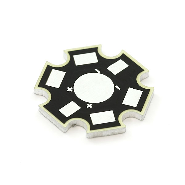
Luxeon Aluminum Breakout
Luxeons get really toasty without proper heat sinking. This breakout board is a special aluminum PCB with isolated traces on the top layer. Designed to dissipate heat from the bottom of the Luxeon to the aluminum backing of the breakout board. For single and multiple LED arrangements. Works great for I and III watt Luxeon LEDs. You will need to attach this board to a larger sink for the V watt Luxeons.
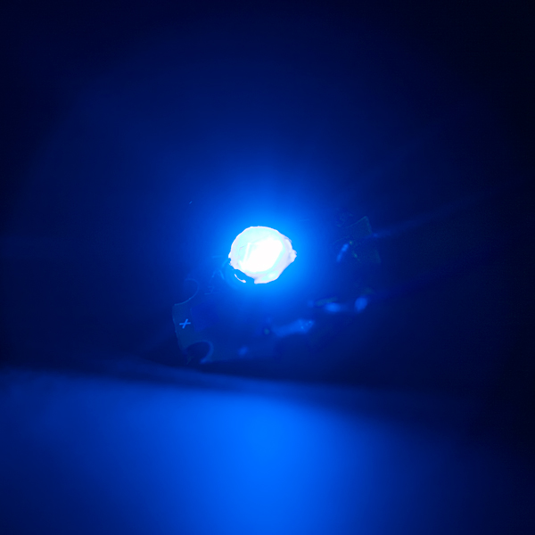
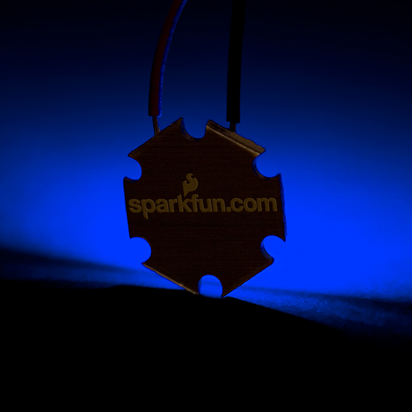
Shown with a Luxeon III Royal Blue LED. We had to put a coffee cup over the LED while testing, it hurt our eyes so badly.
Comments
Looking for answers to technical questions?
We welcome your comments and suggestions below. However, if you are looking for solutions to technical questions please see our Technical Assistance page.
Customer Reviews
No reviews yet.

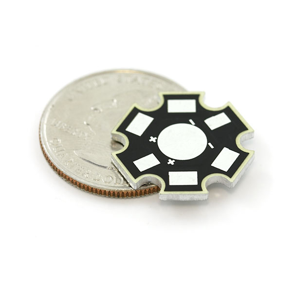
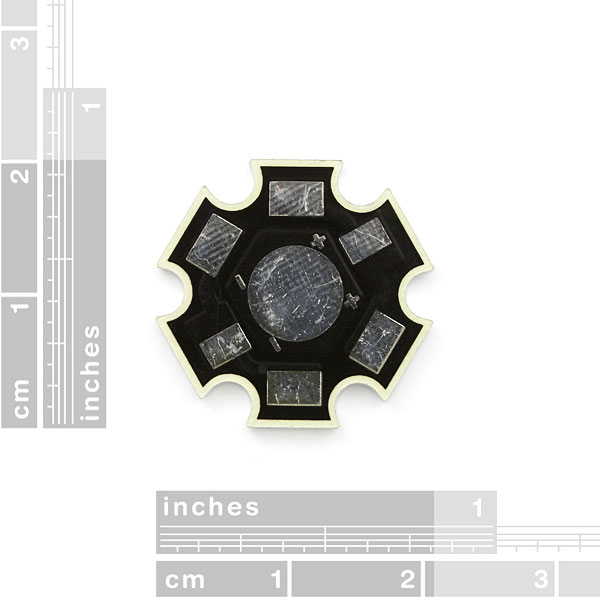
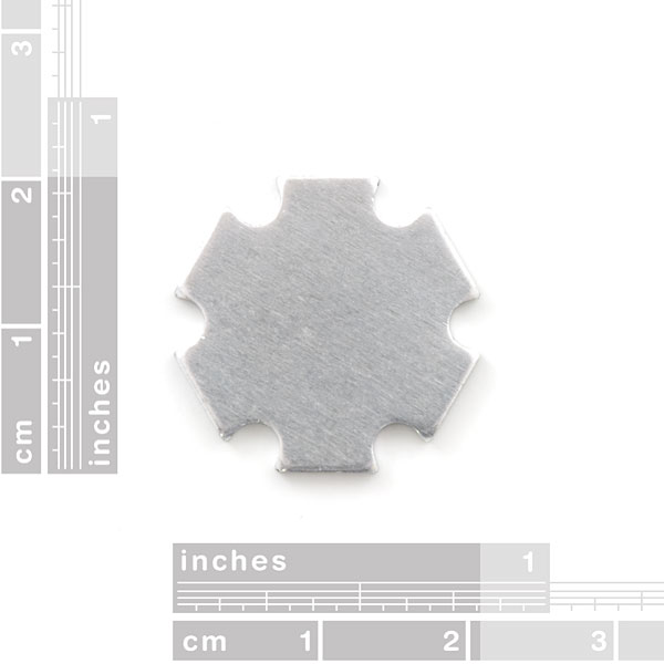
A dimensional drawing wouldn't hurt, but it looks like these follow the de facto standard of 19mm between centers of opposite notches.
Likewise some information about the thermal characteristics is desirable. My nonscientific experience is that the back of the heatsink was too hot to touch comfortably with a 1W LED @ 350mA, strongly implying that the junction temperature was above the 90C that is required to get the 50khour lifetime on the Luxeon LED.
I'm contemplating installation embedded in a wall (no chance of replacement), so lifetime (and therefore temperature) are very important to me.
can we get a clear pic of this thing with LEDs mounted to it but not turned on? I really have no idea how this is supposed to work, how many LEDs can be mounted to it, where the power goes etc ....
Use one breakout for one LED.
The 3 pads on the "+" side are all connected, and the 3 pads on the "-" side are all connected. I assume you're intended to solder the Luxeon's legs to the smaller pads, and solder power to the larger pads. You can test this for yourself by using your meter in continuity-testing mode.
Two pads for each of "+" and "-" are provided so that you can wire several modules in common-cathode or common-anode configuration.