Nordic FOB
Replacement: None. We are no longer building this board. This page is for reference only.
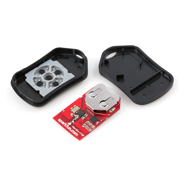
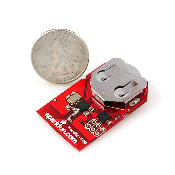
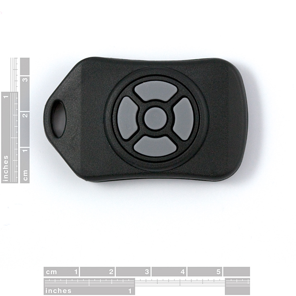
This is a nicely packaged key FOB that contains a Nordic nRF24L01+ radio and a ATtiny24 for control. Press any one of 5 buttons and the ATtiny24 will wake up, transmit the buttons being pressed, a 16-bit integer value of the total button presses since last battery replacement, and then return to low-power sleep. The simple to replace 20mm coin cell will last for over 3 years. This unit comes fully assembled with battery and enclosure. FOB transmission range is quite nice at over 100ft. Use this FOB to communicate with any nRF24L01+ radio module for your next remote control project.
- Small size
- 100ft range
- Pre-programmed
- 4uA average current
- Schematic
- Eagle Files
- Datasheet (nRF24L01)
- Datasheet (ATtiny24)
- FOB firmware
- Example receiver firmware
- Great Nordic tutorials
- Antenna Calculators
Comments
Looking for answers to technical questions?
We welcome your comments and suggestions below. However, if you are looking for solutions to technical questions please see our Technical Assistance page.
Customer Reviews
No reviews yet.


Aw man, found out about this a few years too late! Does anyone know of a similar "nRF24+µC+buttons-size" formula available elsewhere?
SFE still provides us the FOB eagle files and avr firmware and all of the components are available (from others). You should make a couple yourself. They cost around $20 in parts if you do yourself. QFNs are not that hard to solder.
I have several FOBs and still (in 2015) use em and need more. Ive made several more. I sure wish they werent discontinued.
I wish SFE would do another run too. It seems like there is a demand and I haven't found alternatives on the web. Even if they would just sell the circuit board, I think polycase now sells a similar (if not identical) FOB case.
I considered trying to build one myself. I am not bad at soldering, but with this form factor, I think I would botch it up. Being able to solder these components seems a little risky. Solder peaks can do some strange things with RF and some of these components are just too small and close together.
Polycase has the correct case. Soldering the small components can be difficult but it is also completely doable with hot air or a toaster oven. The hardest part for me was getting 0.031" boards made that were both reasonably priced and decent quality. Quotes were from $3 to $100 per board. Ended up getting cheap boards and they are extra delicate during assembly (from heat).
I updated the SFE design to include a couple LEDs for feedback (tx and ack) and changed the mcu. Using the slightly transparent cases from polycase and the LEDs are very nicely visible through the case. Seems to work just fine.
You should just make some.
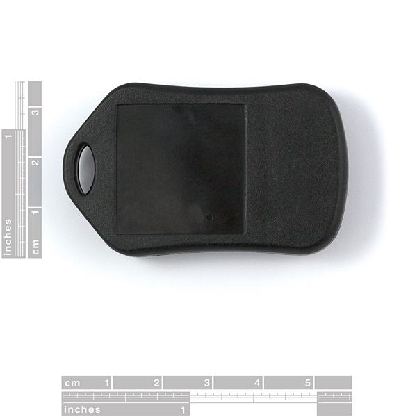
Can we get a photo of the back side of the PCB?
does anything small like this (radio+cpu+input) exist for an xbee?
Got my keyfob today and after some minor tweaking works well.
I modified the keyfob firmware to give a button number (1..5) instead of a bit pattern and set the transmission to 2-byte CRC instead of 1-byte so the transmitted packet is more robust.
My receiver is the sparkfun module..
http://www.sparkfun.com/products/705 using some arduino code for receiving.
Initial range is about 40ft but the setup was not optimal so some more testing required.
Here is an Arduino sketch I modified to allow reception of an off-the-shelf unmodified keyfob. Makes it easier to just get something working.
http://www.s116733136.websitehome.co.uk/KEYFOB_receiver.zip
Enjoy!
What programmer/debugger are you using to program the FOB and what software environment did you use... AVR Studio?
Hi, I used AVRstuduio 4.18 and my programmed is a JTAGICE MKII Chinese clone from MCUzone (I got from ebay). Any in-circuit programmer for atmels should do fine. I did not solder the 6-pin header in the board as it takes too much space and the fob wont click closed. I just held it in place with a bit of a gentle twist on it to ensure contact. Programming only takes a second so its not too fiddly. Enjoy!
Can you also share the code changes you made for the fob itself? That'd be a tremendous help!
Hi, Code files (for AVR studio) are at: http://www.s116733136.websitehome.co.uk/C_keyfob.zip See the readme.txt for what to change. Its almost the same as the original version from sparkfun, just minor changes (and room for more improvement...) Hope it helps..
Thanks!
I used your your code for debounce and its working great.
The solution i posted above from 2010 worked but added too much delay and tended to get annoying when trying to push a button a bunch of times quick. i have removed it and im now using yours.
all better.
mine had some bounce (registered multiple presses) so I had to mod the code. i including a little delay in the code, compiled, and reloaded the new firmware to the fob. now works perfect.
I'm looking for the same. Will you share your code ?
if you the actual firmware let me know. otherwise, theres also a solution in the SFE forums, so search for:
"Debouncing the Nordic FOB"
I added the line:
include
and then after this line:
sbi(PORTB, TX_CSN); //Deselect chip
I added one of these:
_delay_ms(400)
and its been working perfect for my needs.
I used the AVR Studio to edit/compile the code and uploaded the firmware to the FOB with a SFE pocket programmer.
i shoulda pressed preview...
include util/delay.h
with angle brackets where they go...
Nice work! I am glad you were able to get that Fob working better for your project.
Is this item reprogrammable out of the box ? If not, with a little hobbyist tweaking? Thanks!
When programming FOBs I use a male 6 pin header friction fit into holes on fob. To keep the radio chip power within spec (3.6 volts and below), I pulled the +5 pin from the header making it a 5 pin header. The coin cell provides power for the Tiny24 while it is being programmed. The I/O on the 24L01+ is 5 volt tolerant, its power supply pins are not.
It has a standard AVR ISP 6-pin connector (not installed) at location JP1 so the unit can be reprogrammed with the appropriate tool. Can any at Sparfun confirm that the posted firmware is the one shipped?
We keep the FOB firmware listed above updated with what we ship.
Is there any chance of ever getting more of these? I'd love one, or five...
Why are these retired? I got one to test but was hoping to get more :( Also, Does anyone know why the SPI is bit banged in the firmware?
I wouldn't mind seeing this product come back too. I have several projects that are based on this fob and if it breaks, I wouldn't be able to operate them. I wonder if there was too much technical support for it or there were quality issues with it. I know my first one had to be returned.
I've had this fob for over a year but just recently it has not been responding very well to the buttons being pushed. I've cleaned the contacts on the board but it does not seem to help. Any ideas on how to improve the button contacts? Should I try to re-solder them? Has anyone else had similar experiences?
Is the SPI communication with the nrf module bitbanged in the firmware?
Another wish for future revisions: Break out the pins for all the buttons! I had to solder to the itty bitty little traces in order to solder my own external buttons.
I've now bought more of these than any other Sparkfun product, but I wish they were more hackable. (See my prior comment about wanting more IO pins.)
Same here
Flashing of new Firmware didn't work for me with the default settings from JTAG2ICE mkII or the DIAMEX-AVR programmers I have. Neither with avrdude on windows, Linux or Mac; I did also check on Windows 7 with AVR Studio 4.18; What didn't work? All programmers read inconsistent data for the device signature, fuses, memory in general; Then I tried with 115.2 kHz instead of 460.8 kHz for the "ISP Frequency" in AVR Studio 4.18; Now I can read and write, verify the device with my cheap DIAMEX-AVR without any problem ;-)
Now I am connected via Debug Wire to the target. The original code is SO MUCH different from the code I compiled with WinAVR, that I a m totally puzzled. Can anyone explain these differences between the original code in the target after production and the code I get when recompiling the provided firmware with the provided makefile using WinAVR??
The HEX file I generated with WinAVR by make clean, make commands for the Nordic-FOB firmware v11 under Windows 7 are not executing on my Nordic FOB. I can read and reprogram and verify the flashed program, but my receiver is not receiving anything at key press. When I read the program from my other FOB, the hex file looks quite different from what I see in the make generated hex file. However, using the hex file I read from the other production-new FOB and writing it into my experimental FOB makes it work again => my flashing tools work, but the make process or the software provided does not match my FOB hardware. I received my FOB in January 2012. Any help out there?
Simple tutorial and Arduino library:
Nordic FOB with RF24
I struggled with this thing for a while, but finally got it working with an Arduino. Details here:
http://arduino.cc/forum/index.php/topic,84293.0.html
If there's a future revision, I'd like a micro that can spare a few unused GPIO pins. It would allow for some wonderful little hacks to be added. (Piezo key finder! Vibrate receipt confirmation! Two-way communication to an LED or three! Press button to transmit a sensor reading!)
There are some good tutorials about using the keyfob with an Arduino based sensor board and another MSP430 senor board here
and here
Technical specifications says pre-programmed. Can anybody help me ?.
Which channel and TX_ADDR use ?
You'd have to read through the source code to find out..
Channel: 2
TX_ADDR: E7E7E7E7E7
Does anyone have any arduino demo code for communicating with the fob? I've tried everything I can think of using the Arduino Mirf library and one of the modules, and I never receive anything from the fob.
The example Receiver firmware in the link above under the Product Documents looks like it might work - but its in C. Is there a pde version of the above anyone knows about that I can use with the Arduino?
Yeah, Everything has to be just right for communication to work. Maybe someone can answer this question: Does SF still sell anything that is shipped with firmware that with receive factory default firmware fob messages? This is real handy start point. From there if you want to change FOB firmware you can, but can always reload factory firmware and verify your FOB is working.
Yes. Look for the Nordic Serial Interface board. Connects via USB to your PC
How do you know if it's working?
Good Question. SF used to sell a MiRF? module that shipped with firmware that would receive default fob firmware messages. One of their nRF2401 modules would plug into it and blink LEDs and send serial data to terminal to let you know everything worked.
From there careful modification to programs to "keep things working" On FOB, I had no debug facility so I would write data chip EEPROM and read out with programmer.
What micro is the receiver firmware written for?
nevermind
What battery holder does this design use? It seems to be in the Sparkfun Eagle library as BATTERYFOB/BATTERY_20MM_PTH_COMPACT -- but I can't figure out what (say) digikey part this corresponds to.
Seems to be the Keystone 3003, or P/N 3003K-ND at Digikey
Anyone added an LED to this at all? I am assuming that since the chip supports recive that you could send status feedback to the keyfob that an action has happened.
Hi
I am looking for a kit including a Key FOB which should be made to send to and receive an answer from two "clients". The messages from the FOB should be turn-on, turn-off and for each of these the "clients". The "client" should individually return what is the new status after receiving message from the FOB.
Would this platform be a good starting point?
Best regards
Bjorn
Does this specifically require the nRF24L01+ or will it also communicate with the nRF2401A units?
can anyone comment on changing the address of these things? I want to have several art projects operating in close proximity, controlled with multiple FOBs.<br />
<br />
i thought i read somewhere that the four data_array[x] bytes contain the address but cant find the specifics anywhere. im looking in the nRF24L01+ datasheet right now.<br />
<br />
which of the four 0xE7 should I change? and to what?<br />
<br />
thanks.<br />
<br />
To answer my own question. I was able to change the address on the FOB so that I can have two projects operated by two separate FOBs in close proximity. <br />
<br />
Using the AVR Studio, and a SFE pocket AVR programmer: I updated the FOB firmware, modifying the four data_array[x] values from 0xE7 to something else. I did this in the file called nordic-nRF24L01.c. Then loaded into the FOB.<br />
<br />
Can this FOB be flashed via an Arduino in ISP mode ?
Does anybody know any tool I could use to log the messages / packets sent via this Nordic fob?
The point is that we start a new product development that from the HW perspective will be very similar to the fob (with the similar antenna). We'd like to do some research on the RF range and antenna's directionality etc. We already have this fob and now are looking for something able to receive the packets from it (and ideally sent via e.g. serial or usb port).
If you know anything like that (from sparkfun, Nordic or another provider) please let me know!
Thanks,
Tommy
Yes you can why not? You just need to program the SAM7 to decode the 2 byte sequence.
Can I communicate this device with a PC via a "Transceiver nRF24L01 Olimex USB Dongle"? are they compatible?
Would it be possible to get some of these made with ATtiny84's? They're pin compatible with the '24, have enough memory for fun stuff like encryption/rolling code algorithms, and only cost a bit more.
If the t24 can't support well known algorithms for encryption, you can develop easily maths formula very hard to break.
It can be safer to use your own little crypto, than use one with lot of hack tools on the web...
I've updated my FOB, it send the usual button packet and just after a sequence of 2 int.
The first one is increasing each time, the second is a result of maths operation on the first one.
The packet can't be replayed and a hacker will have to wait a loooooot of key presses before being able to reverse-eng the code.
Security through obscurity is the worst argument ever - just look at how quickly the CRYPTO1 algorithm used in RFID cards was broken.
AES 256 will be much more secure than anything most people will come up with and easily fits within 8k(look at Atmel's application note AVR411).
You seem to have missed the whole idea of obscurity.
A high profile, standardised application like RFID is hardly obscure.
Me programming a rolling code of my own on a single fob, for my single door (or computer) is hella obscure ;)
I think you ought to be able to implement SHA1 in the available space. A decent hash algorithm would be all you need to create an OTP-style solution, preventing replay attacks and verifying messages actually come from the fob.
So I can program it with my Pololu USB AVR Programmer?
http://www.pololu.com/catalog/product/1300
Since I have 4 of them!
Ops my mistake.
Avrdude does NOT support ATtiny24 and therefore the STK500 chip for ISP will not work.
You can only program it using the AVRISP mkII In-System Programmer.
Really? The version of avrdude I downloaded in crosspack claims to support ATTiny24.
Hi,
I've used some of the other Nordic 2.4ghz stuff but only sender/receiver in close proximity to each other.
I'm thinking of using this to blib on the courtyard lights - does anyone know how line of sight/or lack off impacts the quoted transmission range?
Thanks
Example application as a robot remote control:
http://robotguy.net/deskpet/dp_proto_rc.jpg
http://robotguy.net/blog/2008/06/19/46/