Laser Module - Red with TTL Control
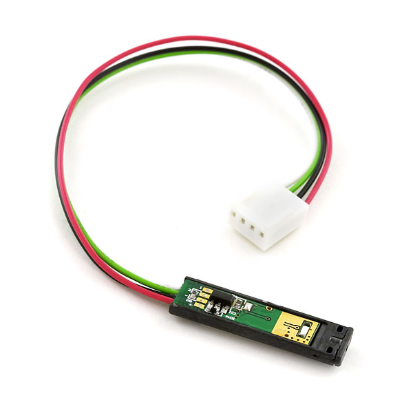
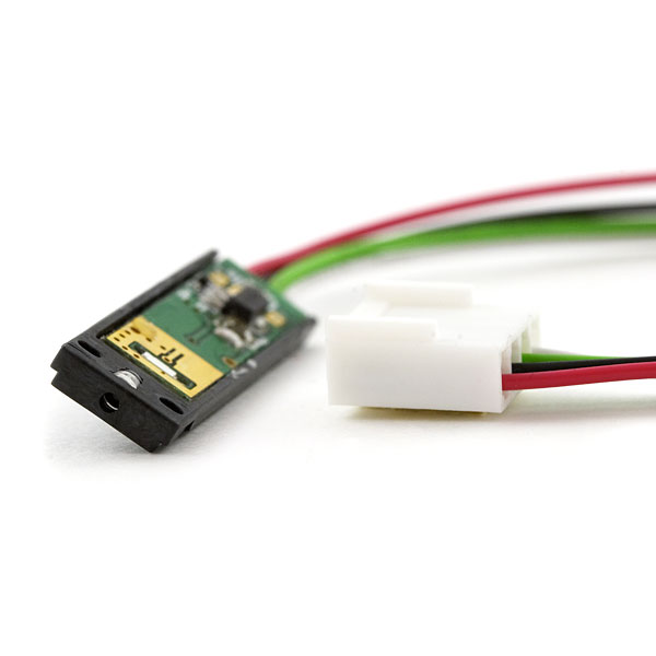
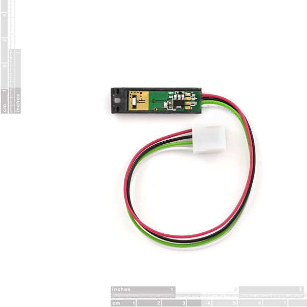
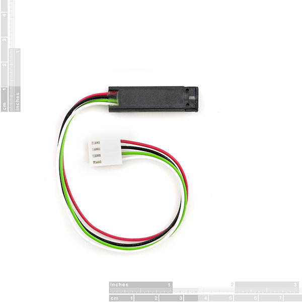
This is the basic laser card module with circuitry built in so that it can be turned on/off with a TTL signal. Includes polarized Molex connector to prevent reverse connection. On-board voltage regulator accepts 5-12VDC. A customer tested these units on his Agilent optical analyzer (Thanks Trenton) The wavelengths were 654.5 nm +/- 0.5 nm at 70 degrees F for the 4 lasers tested.
Note: This is a class 3A laser.
Laser Module - Red with TTL Control Product Help and Resources
Core Skill: Programming
If a board needs code or communicates somehow, you're going to need to know how to program or interface with it. The programming skill is all about communication and code.
Skill Level: Rookie - You will need a better fundamental understand of what code is, and how it works. You will be using beginner-level software and development tools like Arduino. You will be dealing directly with code, but numerous examples and libraries are available. Sensors or shields will communicate with serial or TTL.
See all skill levels
Core Skill: Electrical Prototyping
If it requires power, you need to know how much, what all the pins do, and how to hook it up. You may need to reference datasheets, schematics, and know the ins and outs of electronics.
Skill Level: Competent - You will be required to reference a datasheet or schematic to know how to use a component. Your knowledge of a datasheet will only require basic features like power requirements, pinouts, or communications type. Also, you may need a power supply that?s greater than 12V or more than 1A worth of current.
See all skill levels
Comments
Looking for answers to technical questions?
We welcome your comments and suggestions below. However, if you are looking for solutions to technical questions please see our Technical Assistance page.
Customer Reviews
No reviews yet.


Just a question for safety reason : what is the class of this laser ? We use it in beacons for robotics cup and there are several teams interested in lasers but have safety constraints. Thank you !
Another person interested in the class of this laser! A customer asked me this today.
I would also like to know the class of this laser the wavelength does not help me as I am not a maths wizard
FDA Class 3a ( < 5mW) Hope that helps!
The laser module requires POWER (RED), GROUND (BLACK), and TTL control (WHITE) wire connections.
I'm using the Netduino with the red wire connected to the 5V port, black wire connected to a ground port, and the white wire connected to a digital output port (I used 13 for good luck).
Blink the laser 5 times and then turn off:
public static void Main()
{
OutputPort laser = new OutputPort(Pins.GPIO_PIN_D13, false);
for (int i = 0; i < 5; ++i)
{
laser.Write(false);
Thread.Sleep(250);
laser.Write(true);
Thread.Sleep(250);
}
}
For seasoned users this was probably obvious by looking at the schematic but I'm a newbie and didn't get it at first. Thanks to this site for helping me figure out how to power it:
http://www.robotcraft.ca/webshop/p11/Controlling-Sparkfun-Laser-Module-using-Arduino-WIRING-and-AVR-ATMega644/pages.html
Are these now out of stock? I'm looking to pick up about a dozen.
Will this ever be for sale again?
TheCowGod: So what exactly is the AUX2 pin for? It's just tied through a 10k resistor to ground. Is there any situation where I'd want to do something with that pin? I guess I could use it to detect whether or not the laser is connected.
From the looks of the schematic you can tie Aux1 and Aux2 together to fire the laser if you are not using Aux1 alone for TTL...
What sort of lifetime does this laser have with continual use at 5v?
Can someone suggest something better than the 'Mini Photocell [SEN-09088]' to pick up the receptive end of this signal ? Usually an x86 programmer circumstances have forced me into product design, PIC ASM, etc. and I am trying to put together a simple, but highly accurate 'product detect' on an established project (for which a prox [magnetic or IR] is too inaccurate/far)-- in addition, having a visually detectable source helps alert the user as to where to problem in alignment is.
I know there are professional (much more expensive) off the shelf parts that offer this capability but I figure this is why we are together, learning. I thought of a photo-diode, though for my particular situation it remains a concern about changes in ambient light. Perhaps someone more experienced could speak to the best sensor to use (or why the photocell is sufficient) in varying light situations with the exception of an especially bright opposing light source ?
I would recommend a photodiode such as the not-entirely-accurately-named "Miniature Solar Cell". One way to combat varying illumination is to alternate readings with the laser off and on; this way you have a baseline for the ambient illumination and can look for a change when the laser is on. Of course this means that the transmitter and receiver need to communicate with each other. Another way is to modulate (blink) the laser at a certain frequency, and look for that frequency at the receiver. This is how TV remotes manage to work in horrible ambient illumination. Good luck!
Is there a extension cable for this, or will I need to craft one...
Is it a same laser https://www.sparkfun.com/products/594 with ttl control? 0,8mw ? Thank you
Is there any sort of screening/shielding that could be used to render the laser not/less harmful to human eyes while still maintaining a respectable range?
I just attached this to a Vex Cortex on a digital sensor out port. Connect white to white, red to red, black to black. Ignore green. Setting the sensor port to true/false toggles off/on.
Anyone know the mW rating?
Does anyone know what i could use to detect this beam? I want to send the beam out, have it reflect directly back off of any solid object, then detect and recieve the presence of the reflected beam. Is that possible? What could I use to do that?
Thanks.
Does it need to reflect directly back, or even reflect back at all? If not, you could simply set up a photo-cell on the other side, shroud the photo-cell so you can get a good solid 'connected' signal, then when your beam is broken - the photocell will react accordingly, and you will have your signal.
Looking for the same thing here.
quickstart link busted
what about RGB laser?
Does anyone knows what can I use as a receiver for this laser? I want to detect when the laser is On/Off.
What things can I use for that?
Thanks!
I haven't tried it (yet), but I think a photoresister or a small solar cell should work.
http://sci-toys.com/scitoys/scitoys/light/light.html#laser_communicator
Which spec has this laser? Is it basically the same laser as the COM-00594 red laser with TTL control only?
Mostly interested in wavelengt to find the best bandpass filter.
Thanks in advance!
What's the maximum reliable frequency it can be modulated at?
I feel your pain Byron. To test fire this thing:
red wire (pin 4?, who knows) +5
black wire (pin 3) GND
green wire (pin 2) a complete mystery, not needed
white wire (pin 1) GND works (some low voltage) - apparently you can modulate this thing - haven't tried.
Fortunately it seems to tolerate abuse - at least at 5v.
Does anyone completly understand the interface to this laser. I just picked one up and the schematic is unclear as to necassary pinouts. It seems to me that you need +5V to +12V at Vcc and ground, then it is quite ambiguous as to what else is required? Is Aux 1 really the signal pin and if so what type of TTL signal should I provide? Is it just +5V at Aux 1 continuously when I want the laser on? What is the point of Aux 2? Please help me!!!
What is the response, i.e. what is the frequency/duty cycle you can input to the TTL to have the laser turn on and off in sync.
It sucks being poor, because I can already see a project for this: Yet Another Wireless Com Interface
Two lasers on each side, and two receivers on each side. The reason for two? You toggle the state between the two so that one is ALWAYS ON and one always off during active/valid signals. You can tell when valid data is coming by connecting the two receiver outputs to each leg of an XOR gate for "ACTIVE," and pick one of the two for the actual data. Instant 2-wire serial (w/o handshake)! You can bit-bang easily if you shut BOTH lasers off between bits (wait for an "active" before reading the bit).
Fog, problem. Rain, problem (noisy I'm thinking). Trees, problem (especially with wind). Passer's-by, problem. BUT, under the right conditions you could tell there was something wrong if you're expecting data and the active line goes quiet.
I dunno, just thinking out loud...
What's the maximum length on these things, anyways? Anyone played with them long-range?
bout a mile i got one (at night low humidity low partical count)
I meant to say "maximum range", not length.
How does the sending layser knows when the other laysers isen't recieving?
So what exactly is the AUX2 pin for? It's just tied through a 10k resistor to ground. Is there any situation where I'd want to do something with that pin? I guess I could use it to detect whether or not the laser is connected.