Softpot Rotary Potentiometer
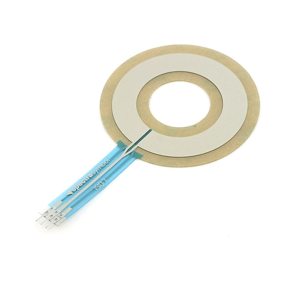
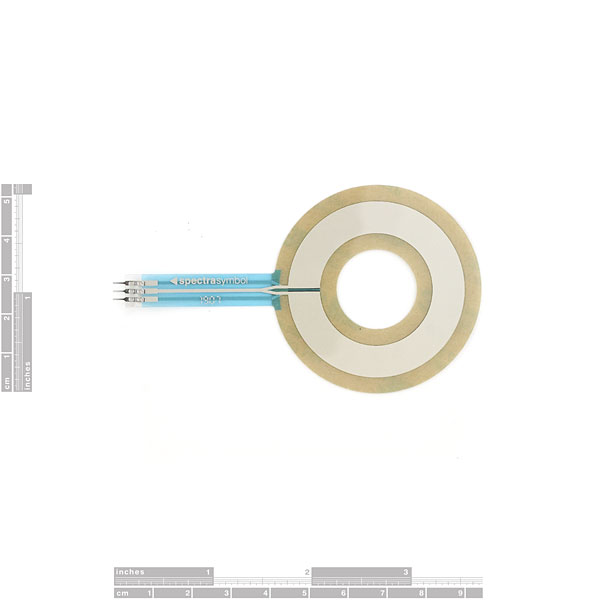
These are very thin variable potentiometers. By pressing down on various parts of the rotary dial, the resistance linearly changes from 100Ohms to 10,000Ohms allowing the user to very accurately calculate the relative position on the rotary. Can be used as an accurate positional indicator for rotational items, variable user input (volume level input for example), straight user input (multiple button areas translate to given resistance levels), and many other applications.
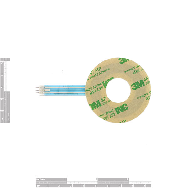
Unit comes with adhesive backing. Connector is 0.1" spaced and bread board friendly.
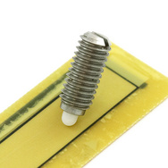
Note: These potentiometers work great with a finger, or stylus. For premium repeatability, the wiper listed below is perfect for machine and object positioning.
Softpot Rotary Potentiometer Product Help and Resources
SoftPot Hookup Guide
May 5, 2016
Equip your Arduino project with a sliding soft potentiometer to monitor position or adding linear control to your project.
Core Skill: Electrical Prototyping
If it requires power, you need to know how much, what all the pins do, and how to hook it up. You may need to reference datasheets, schematics, and know the ins and outs of electronics.
Skill Level: Noob - You don't need to reference a datasheet, but you will need to know basic power requirements.
See all skill levels
Comments
Looking for answers to technical questions?
We welcome your comments and suggestions below. However, if you are looking for solutions to technical questions please see our Technical Assistance page.
Customer Reviews
No reviews yet.


I am building an elevation and azimuth rotor for moving a small Antenna to track satalites for ham radio. I need a feed back signal So the controller knows where the antenna is. Would this potentiometer Work if placed between the upper and lower sections of the rotor. I am looking solutions To this problem but trying not to over complicate things. I will be using an arduino uno With a motor shield as an interface.
I would recommend using a stepper motor. It will allow you to position the motor with precision.
i bought one of these a while back, and am hooking it up to an arduino. i read through the comments and as suggested i have
pin 1 >1k resistor > +5v pin 2 >1k resistor > analog 0 pin 3 > ground
as i read the sensor, the output starts at around 500, and slowly sinks to zero over the course of 30 seconds, and when i tap any location of the potentiometer, the reading jumps to 1023 and declines at the same rate to zero. any clue what I've done wrong? could it be burned out? it recognizes presses, just not positional readings...
What connectors are on the end of these things. They look like solder tabs but I just want to be sure.
can i use it to control this? http://www.sparkfun.com/products/10407
So I purchased this without really paying attention to the size. Turns out it's way to big for my needs (waste of money). Thank god sparkfun takes pictures with the comparison coin now a days.
We also include full dimensionals on almost all the products we sell. Sorry it didn't work for you.
Would this work as a direct electronic replacement for the potentiometer in a standard servo? I want to move the feedback outside the servo to the actual joint. Something that won't be effected by water would also be very useful.
If you opened your servo(Voiding the warranty) and found that it used a nearly identical range than maybe, but this is just an idea.
A very pointless question, but is this or similar technology the stuff they use on some iPods to make the slide-your-finger-in-a-circle method of scrolling through menus?
Mostly pointless because the answer is already in earlier comments? Scroll up ;)
( that and this product is out of stock, but there's always http://www.sparkfun.com/products/9074 )
Uggh. Unless you got one of those magic-blue-smoke-refilling kits, you need to use a ~1K resistor between the collector pin of the softPot and the microcontroller input pin.
If you don't use a resistor, you will burn the thing. Not clear in the datasheet. The issue being the resistance between V+ and the collector goes all the way down to 0 ohms at one extreme. Uh-oh. Things got hot fast.
Cheers
I figured this out also. Except I had read your comment first and had a 1k but was looking to get as close to zero on the read when its floating. Mine kept steadily slowly rolled away from 300 to approx 100-150. So put in a 100 ohm. The problem occurred when my finger crossed over the blue divider line there are two burn marks on either side of it now. I tried plugging it back it but it started heating up again. Apparently this isn't enough to stop it from frying. Lesson learned.
update: I'm not sure if I got a defect one or what but I've managed to get mine working again. I used a pair of scissors to cut right down to the blue line, almost to where the two sensor traces intersect. I then put a piece of eletrical tape on one side to prevent the V+ from jumping to GND.
Success!
Interesting solution KHartley. I'll have to give that a try.
In addition to the current limiting resistor between collector and GND, I have found that you need another resistor between V+ and the Vin pin of the SoftPot. This is necessary because when your finger crosses the small gap at the bottom of the SoftPot, you are bypassing the internal resistance and shorting V+ to GND.
I imagine with a mechanical "wiper" this would not be an issue, but your finger has a wide enough contact area to straddle the gap.
So in short:
(V+)-----------(1K)------(Pin 1 of SoftPot)
(AnalogIn)-----(1K)------(Pin 2 of SoftPot)
(GND)--------------------(Pin 3 of SoftPot)
hope that saves somebody $15!
cheers
Thanks so much, you definitively saved me 15 dollars. Probably even more sense I take the "Thomas Edison" approach to all my problems :P.
Is there a 360 degree mulit-turn SoftPot??? I know Sensofoil makes one but does Spectra Symbol? Also, does anyone know if they make this one with a larger ID???
Can I place a thin piece of plastic over this to hide it? Or will it not work correctly if I do?
No guarantees, but I'd imagine that if you do so, it would more evenly distribute the pressure of a finger, confusing the sensor and reducing accuracy. In short....probably not. But don't take my word for it.
You could however, use a capacitive sensor like an iPod uses and place material over it and have it still work.
Hi there - I just burned one of those by connecting it as follows: pin1 to +5V, pin3 to ground, collector (pin2) to the analog input of a PIC ds30f4011.
Obviously I did something wrong. I am ordering a new one but would like to know how to properly connect these sensors? It seems other people had this issue (http://www.arduino.cc/cgi-bin/yabb2/YaBB.pl?num=1234777997/30) but I could not really find a satisfactory answer over there - and this information would be handy on this page (mis-configuration of the PIC analog input is unlikely: it does measure voltage properly when using regular resistors). I did verify the collector pin with a ohmmeter before wiring...
Any advice?
Thanks!
This is definitely not the same sensor that the iPod uses. iPod wheels use capacitive sensors (http://electronics.howstuffworks.com/ipod4.htm) rather than resistive sensors like this one.
ChrisZ: I'm thinking these would be great to use for trying to duplicate the Ipod rotary navigation "button".
I just was thinking the same before I opend the comments.
Not trowing away a broken ipod was a good thing.
Does anyone knows if the spec's are simillar of the touchweel from an ipod?
Nope, they're completely different. iPod touchwheels detect relative position rather than absolute. That is, they measure the movement of the finger rather than the position of it.
You just need to calculate the change in absolute position to get a ralative position, I would imagine that this would be exactly the same type of touch sensor the Ipod uses. Somebody correct me if I'm wrong, but in the product description it even says "allowing the user to very accurately calculate the relative position on the rotary".
I saw a show on how Ipods were made and if I remember they didn't use anything like this, it seemed more like a string of those capacitive touch sensors you find on calculators and such.
Yeah, that would also be extremely more expensive than this guy, too much for a cheap widget ;-)
I'm thinking these would be great to use for trying to duplicate the Ipod rotary navigation "button".