SparkFun AVR Stick
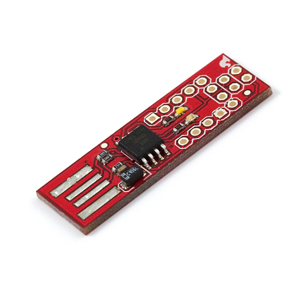
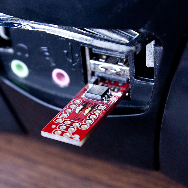
The SparkFun AVR Stick is a simple data logging device that instantiates itself as an HID keyboard and reports the voltages, along with a 'timestamp,' from two pins on an ATtiny85. The device uses open source firmware availabe from Objective Development (http://www.obdev.at/vusb/) called V-USB to implement the USB 1.1 standard. The code that runs the application was based on the EasyLogger example application from Objective development.
The default firmware runs simply enough: plug it in to a USB port on your computer, after the computer recognizes the device as a keyboard it will automatically start reporting the voltages. To get a series of measurements, open up a text or spreadsheet editor and plug the AVR stick in. The AVR Stick will automatically start inputting the voltage values to whatever program is active on the computer. The ADC is configured to use a 2.56V reference voltage, so don't try measuring anything higher than that without modifying the code!
This thing is meant to be hacked! Visit the Objective Development website to learn how others have used the USB stack to implement miscellaneous HID projects like keyboards, mice, joysticks, etc., etc., etc...
- Schematic
- Eagle Files
- Arduino Quick Reference (ATtiny85)
- GitHub
SparkFun AVR Stick Product Help and Resources
Core Skill: Soldering
This skill defines how difficult the soldering is on a particular product. It might be a couple simple solder joints, or require special reflow tools.
Skill Level: Noob - Some basic soldering is required, but it is limited to a just a few pins, basic through-hole soldering, and couple (if any) polarized components. A basic soldering iron is all you should need.
See all skill levels
Core Skill: Programming
If a board needs code or communicates somehow, you're going to need to know how to program or interface with it. The programming skill is all about communication and code.
Skill Level: Competent - The toolchain for programming is a bit more complex and will examples may not be explicitly provided for you. You will be required to have a fundamental knowledge of programming and be required to provide your own code. You may need to modify existing libraries or code to work with your specific hardware. Sensor and hardware interfaces will be SPI or I2C.
See all skill levels
Core Skill: Electrical Prototyping
If it requires power, you need to know how much, what all the pins do, and how to hook it up. You may need to reference datasheets, schematics, and know the ins and outs of electronics.
Skill Level: Noob - You don't need to reference a datasheet, but you will need to know basic power requirements.
See all skill levels
Comments
Looking for answers to technical questions?
We welcome your comments and suggestions below. However, if you are looking for solutions to technical questions please see our Technical Assistance page.
Customer Reviews
No reviews yet.

I purchased the SparkFun AVR Stick back in Jan 2014, just getting around to doing something useful with it (useful to me anyway). I worked for a large company that required a ten minute lock screen on all laptops, even if you worked from home. It was quite tedious to relogin every time I stepped away from my desk for a bit. Years ago, I had originally hacked together an attiny85 used as a timer to energize a small vibration motor every five minutes. It was taped to the bottom of a USB mouse and shook the cursor just enough often enough to keep the screen from timing out. As it was mechanical and being taped to the bottom of a mouse was not exactly ideal, periodic failures occurred every couple of years. (people, my boss, could hear it on calls too) I wanted to make something solid state.
That's where the AVR Stick came in. I originally planned to emulate a mouse with it, but it turned out using the keyboard functionality already built in was much easier. It's now coded to send two Scroll Lock codes back to back about once every five minutes. Even if there were some actual use for the Scroll Lock key, the two codes back to back would rapidly toggle to the existing state.
I used SparkFun's Tiny AVR Programmer to reprogram the AVR Stick along with the Arduino compiler. To get started I soldered ISP headers onto the Tiny AVR Programmer and the AVR Stick and made a suitable 1x6 to 2x3 jumper cable. Naturally I plugged in the cable backwards once and fried the smd attiny85 on the AVR Stick; one of the capacitors got damaged in the process as well. (After I fixed the AVR Stick, I checked for continuity from VCC/GND/RST on the programmer to the stick every single time I used the programmer) After destroying the original chip, the overall exercise now included my first smd solder paste/hot air rework. In the end I also added a 16MHz ceramic resonator and a proper USB connector.
The link below has some pics. 1 before solder rework 2 after solder rework 3 finished AVR stick 4 stick with programmer
http://www.cscientific.com/home/avrstick/index.html
Using a lot of trial and error I hacked out the code solution I was looking for with the supplied code base and Arduino programmer. Thanks SparkFun for leaving retired product information online, otherwise I'd have gotten nowhere.
Here are a few of the hurdles I encountered in the programming process.
The first confusing thing was related to C++ which is apparently the default for Arduino. I'm not sure you can even change the default to C, I couldn't find the setting to do so in any case. The problem was C++ name mangling caused functions to not be found. That turned out to be a pretty easy fix, I just wrapped a couple of the header includes in 'extern "C"' in the main .ino:
Another issue from me was the clock speed. The code indicates that you can use the internal attiny85 clock for timing but that didn't work for me. Windows would fail it saying that it didn't recognize the device. In the end I used a 16MHz ceramic resonator and it worked for Windows, there is a place in usbconfig.h where the clock speed must be specified.
The rest was mostly just enough code study to get it to do what I wanted. I commented out the timer and adc calls as they weren't necessary or advantageous for my purposes. I added one small delay in the main for loop and a condition/counter that gave me approx. a five minute interval. The code '71' is Scroll Lock:
Cool write up.
For those who might be interested, as a demo I ported Till Harbaum's i2c-tiny-usb code to run on this board. A brief description of it is posted at http://ceworkbench.wordpress.com/2011/11/11/i2c-for-the-avr-stick/; the updated code is available as a project on the V-USB wiki.
Would it be possible to port i2c-tiny-usb to Little Wire hardware?
I don't have a Little Wire to try it out but comparing the schematics, I suspect it would.
Could anybody please tell me how to connect to this chip? Would jump wire do the job? Do I need soldering? I am a newbie, sorry for the silly questions.
It connects to your computer via a USB port. Simply plug it into your computer right side up as shown in this picture.
To connect the IO pins without soldering, you can use some Solderless Headers and Jumper Wires.
thank you so much. I have another newbie question which I help you can help.
I am trying to connect this current sensor http://www.sparkfun.com/products/8882
to this AVR stick. The current sensor outputs voltage signals, which I think would be recorded by this stick.
However, I don't know which pins on the AVR stick I should use. Could you help me on that?
You can use
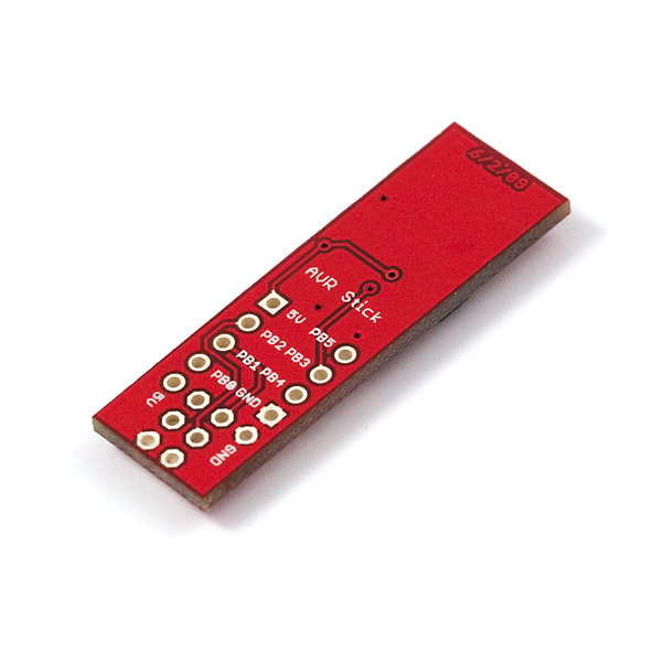
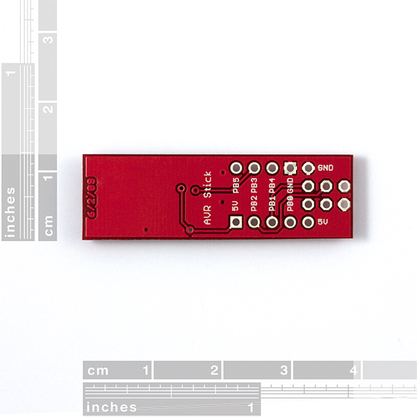
PB3, orPB4to measure voltages.PB4is ideal because there is an LED onPB3.It would be neat to use a TSSOP ATtiny45 and a thin board and have the whole thing fit inside the connector.
On Mac OS (Leopard), this only works thru a USB hub, not connected directly to a USB port on Mac. Just like the Pocket AVR Programmer does. Interesting.
I guess the USB connector on the board can be made better by gluing a piece of a PCB etc on bottom of the connector, to make it thicker.
Hmmm... strangely enough, I'm having the same problem with my wireless mouse, of all things. I think it might have something to do with the amount of power being supplied to the device. It supplies less power than it should, unless the device is a hub. Anyone know more about this?
That's because a lot of V-USB projects use goofy things like LED's instead of diodes, or crazy resistor voltage dividers. All you need to do is use 3.6v zeners and clamp the data lines to ground. For clarity, stripe of diode to data line, other end to ground. That is IN PLACE OF those stupid LED's (LED 1 & 2 on the schematic, and yes, reversed orientation than shown, STRIPE to D+&-). I had to make a modded USB cable with the zeners going to ground to get the pocket programmer to work in linux.
And yes, I know an LED is technically a diode but it is NOT a Zener diode, which is more standard USB circuit design (or, at least was, now we got FTDI and USB enabled mcu's). Josh, I'm willing to bet that mouse is reallllllllly cheap? :)
Does anyone have the power draw for this board? I am looking to replace a teensy with something a little more efficient and I was wondering if this would qualify.
Can the "Trinket" image (inc. bootloader) be installed on this?
For a new comer in AVR(ATTiny85), once you have an AVR Programmer and an USB Stick, what is the simplest way to compile and write a program into. Is there a simple tutorial to do that ? (Compilation, writing...)
Thx
Why cant i program this with a USBTiny ? avrdude fails to initialize? Please help
I've put this circuit on my own pcb, and loaded the firmware and I'm not getting anything. The computer doesn't recognize it as an HID device... Any suggestions? Anyone else had similar problems?
I bought this AVR Stick but have had no success in programming it. I am trying to first read/write its registers from a Linux machine. I connected the board to a STK500v2 programmer and tried to reload a modified firmware using avrdude. But couldn't get some signature error (avrdude asking me to recheck connections).
Can someone tell me if STK500 is the right programmer for this? If not, what should I use? Is there a step by step tutorial that shows how to program this hardware?
Thanks in advance for any help.
Just be warned; this stick will not readily plug into an Apple Air due to the PCB beeing ½mm too wide. :(
maybe, someone could port the Little Wire firmware to AVR Stick?
http://littlewire.cc/
Not really - a lot of littlewire's functionality comes from special hardware features which only work on certain pins. You would be better off just installing littlewire on a digispark if cost is a concern - they are $8 each and electrically compatible with littlewire firmware.
I made a tiny85 USB bootloader that is compatible with this board. Check it out here: http://embedded-creations.com/projects/attiny85-usb-bootloader-overview/
Once loaded onto the board, you should be able to update your application using a modified version of AVRDUDE (a precompiled .exe for windows is included)
There are precompiled binaries in the \firmware\hexfiles\ directory. "tiny85_165mhz_configuration1.hex" is the right binary for the AVR Stick.
Please let me know how it works for you, either here or on my site!
Was able to get this project loaded and compiling with AVR Studio 5. Downloading using AVR Dragon via ISP.
To solve this issue you can soldier a USB Male A connector at the end. If anyone needs info post and ill put it up on my site.
This project was inspiration for my attempt at a USB power switch. I was able to build a simple, single output switch (for switching power on another USB port) using an ATTiny2313. It also uses the V-USB driver and the latest libusb-win32 drivers. Thanks for all the great projects and open designs, it's a great help to amateur hobbyists like myself.
This board is a little finnicky to plug in. I wonder if it would work better on a 2mm PCB instead of 1.6mm. If you measure a USB connector they are generally around 2mm thick. Also have you guys considered using an ENIG board which may contact better than their current HASL finish?
It would be cool if you could
Program it via USB! Then you would have a $10 micro with the ability to hook up other stuff via USB!
Or you can get the DigiSpark now for $8! http://digistump.com - a programmable attiny85 board, with a voltage regulator included too and arduino app support.
The ATTINY85 should have more than enough codespace to concurrently run a USB bootloader (e.g. BootloaderHID) along with the existing USB datalogging code. Now if only I could get the V-USB projects to run in AVR Studio...
The ATTINY85 lacks hardware bootloader support essential to running bootloadHID and just about any other boot loader. To bootload the tiny85 you need to use a specially optimised tiny bootloader - https://github.com/Bluebie/micronucleus-t85 is currently the smallest, but in it's default configuration it expects USB signals on pb3 and pb4 (like on the LittleWire.cc and DigiSpark), so you'll need to change firmware/bootloaderconfig.h's configuration to use the wiring of the AVR Stick and recompile.
Micronucleus is currently the smallest usb bootloader for tiny85. There are some much smaller serial bootloaders like tinysafeboot. I don't know of any tiny85 bootloaders which support avrdude. All the USB ones require their own program, but micronucleus' program has been built and tested on Mac, Windows, and Linux with no issues. :)
figured out the solution to the PB3 input issue..... figured i'd share here for all who are interested (and sparkfun so they can fix the code)
took me longer than expected because the YELLOW_LED and WHITE_LED constants refer to the other LED (YELLOW has the correct value for WHITE and visa versa).
as expected it was the line
DDRB &= ~(1<<4);
that needed fixing. if you're going to leave the rest of the code the way it is (aka not fix the constants) you change that line to look like this:
DDRB &= ~(1<<4 | 1<<WHITE_LED);
(note that i used white because it contains the correct offset for yellow)
once you do that recompile and download and it works like a dream! still a nifty product to help me start working with some new sensors for a project i'm working on, but a PITA to setup right. please fix the code sparkfun!
according to your own code (if i understand it right) PB3 never gets reconfigured as an input. (aka DDRB's bit for PB3 is still set to 1) while you may still be using that pin for input (clearly because the ADC is still taking samples off of it) you also have it defined as an output which is in a low-state at that point in time. so anything connected to PB3 with a fresh out of the box AVR stick is bound to only read one set of analog data values with full resolution and range.
here's the bit of code in particular.
DDRB &= ~(1<<4);
that resets the PB4 bit back to zero (configuring it for input) but not PB3.
so unfortunately all these people who have bought AVR sticks have been getting essentially half an AVR stick, because of what looks like one line of code. i'm glad i bought an ISP programmer, because i'm going to need to fix this.
As long as you have an available 'tight' USB connection this little circuit worked well today on Ubuntu 10.10, Windows 7 32 and Ubuntu 10.10 running as a VM on VMplayer 3.14 under Windows 7. In 2 of the 3 cases it was via an external USB hub, the third was native to the motherboard. Need a little more time to see if the readings make sense, but it worked well loading a spreadsheet, and a simple text file, tab delimited.
No external driver required.
I just found out how much i love this little guy. I hacked the 4-key keyboard code up to use just PB3 and PB4. I cut the trace for the yellow LED. Loaded the fuse setting and the code. works perfectly out of the box. just add a switch or two. I have mine bread board enabled, so it's a dream...
http://blog.flipwork.nl/?x=entry:entry100224-003937
First, with some headers it will fit on a breadboard, nice job sparkfun.
Second, if you want a bit of durability, and want it to stay in the usb socket, i suggest the usb A connector PRT-00437, bend the pins a little, cut the plastic tabs.. i do recommend gluing it.
Nope. Even doing that, I can't get anything like full scale on that channel. That probably means the shipped firmware keeps it configured as an output and I am trying and failing to swamp that out with my driver.
If / when I get a six-pin programmer going, I might try to load the firmware linked to up at top of this page and see if the second channel works as advertised with my cut LED trace mod.
Until then, I have to also give this product a bad review for the hostile out-of-the box experience and a rosy description of function not in evidence. This is the first time I've ever felt really let down by a Sparkfun product. Bummer.
ok, i'm having the same issue. soooo frustrating. been trying to test my thumb slide joystick (which works, i tested the resistances manually) to see how easy it would be to make it a mouse for a project i'm working on..... so i was a little pissed when the third column only shows values from 5-20 because it's still apparently turned on as an output and so is being pulled low internally? or something similar.
anyways, i did order one of the pocket AVR programmers when i bought mine so i'm going to try what you suggest and see if i can get this bloody thing to cooperate.
Jimbo, all:
I thought I'd leave a little trace of my work trying to get the promised two analog channels.
I bought two of what look like the 1.1 version (no blue LEDs) quite some time ago. I too found the "connector" to be marginal, and I didn't understand from the schematic what the second analog input channel, if any, is. I'd get strings of the form
readingnumber PB4reading 0
But from the published schematic nothing looks like a free analog input. All those zeroes in the third column made me wonder if it were a digital input. But then, every once in a while by running my fingers around and getting resistive or capacitive coupling, I get something like
readingnumber PB4reading 2
Things that make you go "Hmmm". Whatever the second channel is, it's much less sensitive (lower Z, I guess?). From mjy58's commentary it might be PB3, I suppose.
I can't tell how to get the second channel to work safely from the info Sparkfun provided and pointed to. I can get one channel, so it's not utterly useless. And it's a cute hack. Going from what mjy58 wrote and other hints on linked pages:
From the fact that the firmware on the ones I've got seems to flash the yellow LED on PB3 immediately after connection to the USB port, even if I cut the trace to get rid of the 470 ohm + yellow LED load on that pin, whatever analog source I connect is gonna see that pin treated as an active high output for a moment after plugin. I suppose that can be mitigated with a 10k to 20k resistor fed by a buffer amp.
There are worse things than a little signal conditioning, I suppose.
Hi guys, i'm playing for a while with VUSB with at{mega|tiny}.
This is the first time i see an vusb implementation without an external crystal and i'm wondering how it could works.
In the Makefile there is the -DFCPU=16500000 define, and in the code there is the TCCR1 = 0x0b; directive...is this enough (in conjunction with fuses settings) to run the attiny @ 16,5mHz ?
Thanks in advance,
enrico.
P.S. sorry for my lame english.
I found the explanation here: http://vusb.wikidot.com/examples#toc4
Thanks, enrico.
hey guys thought of a project but im new at micro controllers and programing and electronics... well you get the idea. but would there be a way to add a female usb port to this and read voltages from that and send them to the computer?
Can anyone point me in the right direction on how to program this AVR Stick, I have programmed other AVR micros but only with the use of a serial connection. I am assuming you can program the AVR Stick Via the computer USB??
There's a 6 pin ISP header at the end. You can use this with a programmer (like the pocket programmer) to program it.
http://www.sparkfun.com/commerce/product_info.php?products_id=9231
I see the 6 holes for the isp on this. Do I need to get some male header pins (http://www.sparkfun.com/commerce/product_info.php?products_id=778) to adapt it to the female connector on the programmer? Or does the pocket programmer include something that will work with the holes?
You'll need some male header pins. Pro tip: all you need is one set: if you insert them into the end of your programmer cable (so that it effectively has male outputs instead of female) you can just press the end of the programmer against the holes in the PCB while you're programming, you don't actually need to solder the header in place.
Has anyone had any luck reprogramming the device? I can get the code to compile fine in CodevisionAVR, but can't get the AVRISPmkII to communicate...? Yes, I have upgraded the firmware...any help pls?
Plugged the AVR stick in started logging straight away - 0 on both PB4 and PB3. Couple of resistors on PB4 started logging 2557 corresponding to 2.57 volts.
However, the only way I can get PB3 to change from 0 is to put much too low value resistor to Vcc. PB3 appears to be sinking current??
Is it configured as an output to drive the LED?
This violates the USB electrical spec by driving 5V onto D+/D- (they are 3.3V signals). USB hosts are required to withstand 5.25V on D+/D-for up to 24 hours -- but not indefinitely. Might be wise to connect this through a $5 USB hub instead of directly onto your $2500 iComputer. Or, add dropdown diodes or a proper 3.3V Vreg for the AVR.
The D+ and D- pins are connected to Blue LEDs...which have roughly 3.3V forward drop. The LED is acting as the voltage reg.
This doesn't seem like such a good idea to me... But I could be wrong.
First of all, 25 mA off a data line is not generally a good idea. I'm not sure what the USB standard specifies.
Also, although I'm pretty sure the USB standard requires 68 ohm resistors on both sides of data lines, if a data line somehow gets pulled high without resistance or with
I'm not fully sure where the 25mA is from but I do know that the ATtiny85 can handle 40mA both in and out on i/o.
I just noticed this. Very clever!
BTW, don't waste your time and try to use a USB port as a power supply while programming it. It just won't work. For one, it'll start thrashing on its virtual keyboard, causing all sorts of chaos. More importantly, one of the USB data lines is shared with one of the ISP signals. It took me a few hours of banging my head before I carefully looked at the schematic and realized this.
Hi,
I've got the following error msg from AVR Studio, when "Rebuild All" using WinAVR as the external compiler: c:/winavr-20090313/bin/../lib/gcc/avr/4.3.2/../../../../avr/lib/avr25/crttn85.o:(.init9+0x0): undefined reference to `main'
Any idea?
Happy New Year!
Mis-LED.
The schematic shows 4 LEDs. There are apparently only two on the actual board.
Is it too much to ask for a schematic which corresponds to the product?
(I suspect the reasons for it, but it would be nice if it was noted somewhere)
Whew, that was quick. We just built a new revision this board yesterday to add a couple new LEDs, the schematic link was updated to reflect that.
Here's a link to the older version of the schematic: http://www.sparkfun.com/datasheets/Widgets/AVR-Stick-v11.pdf
I think the same hardware can be more usefull with an i2c firmware provided at http://www.harbaum.org/till/i2c_tiny_usb/ rather than a analog logger.
There are a few things to note:
-Mislabeled White/Yellow LED in code.
-For a 'hackable' item, this should have more documented code. Especially with regards to where to enable the second ADC channel and the test bed code parts. Lower the barrier to entry and you will sell more.
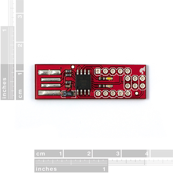
-The layout is all funky. Look at the USB connector, it's not centered across the width of the board.
got mine today. works great. super cool to be able to do usb with 2 i/o and 3 resistors.
Here is a site that uses the same micro and implements an oscilloscope out of it.
http://yveslebrac.blogspot.com/2008/10/cheapest-dual-trace-scope-in-galaxy.html
I'm afraid I'm going to have to give this thing a bad review.
I did get it to work, but only after providing my own USB cable (pigtaled to fit in a breadboard) and resistors. Basically all I'm using is the tiny85 and the filter capacitors. And that just isn't worth ten bucks.
The problem arises from the 'USB' connector on the board, it never did work for me, even after adding a little solder, a lot of solder, removing solder, trying to level the solder out with a razor blade . . . until I lifted a trace and made the usb end worthless.
IMO, buy yourself a ATtiny85 (or 45) and put it together yourself.
(btw, the firmware worked fine after getting the physical stuff in order)
oooh i wanted one so bad!!!!
max/msp has a great implementation of the HID stack, so you can probably plug several of these in, and route to different places
when are you getting more!
-d0c