7-Segment Display - 4-Digit (Yellow)
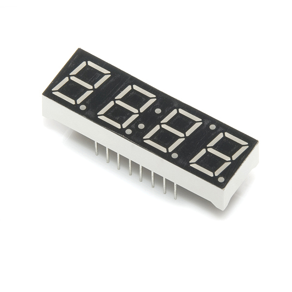
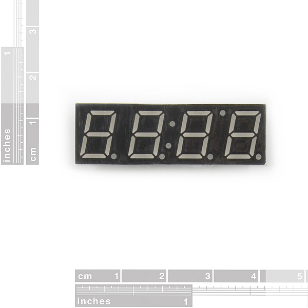
This is a basic, 4-digit 7-segment display - yellow in color. It has a common anode. The display features one decimal point per digit, and individually controllable apostrophe and colon points.
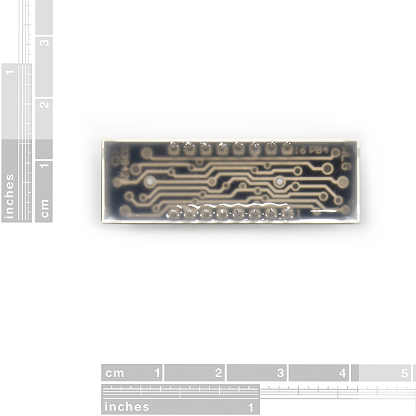
The LEDs have a forward voltage of 2.1VDC and a max forward current of 20mA. The hardware interface is sixteen (two rows of eight) through-hole pins.
- Overall Display: 40.18 x 12.8 mm (1.58 x 0.50")
- Digit Height: 10mm (0.39")
7-Segment Display - 4-Digit (Yellow) Product Help and Resources
Core Skill: Electrical Prototyping
If it requires power, you need to know how much, what all the pins do, and how to hook it up. You may need to reference datasheets, schematics, and know the ins and outs of electronics.
Skill Level: Competent - You will be required to reference a datasheet or schematic to know how to use a component. Your knowledge of a datasheet will only require basic features like power requirements, pinouts, or communications type. Also, you may need a power supply that?s greater than 12V or more than 1A worth of current.
See all skill levels
Comments
Looking for answers to technical questions?
We welcome your comments and suggestions below. However, if you are looking for solutions to technical questions please see our Technical Assistance page.
Customer Reviews
No reviews yet.


Hello ! By any chance you could get some FYQ-3942BUA ? I believe these are Amber instead of yellow ... I’m preparing a car project and I need Amber to match the dashboard lights on my Renault Clio =)
... is there anybody out there ? ;)
My problem is ... eBay ! Ahahah this one seller sent two of a kind and one of another, they don’t match and I believe there’s even a Typo on the middle one markings ! All three don’t match the pics in the eBay listing ... no replaceable battery ... oh well ... ;) https://www.flickr.com/gp/danielnogueira78/Ga3UTA and https://www.flickr.com/gp/danielnogueira78/wKN83a
I bought this a little while ago. I still have one problem though... I cant figure it out. Which pin is which? SO CONFUSED!
The datasheet linked to here is for a LTC-4727JS display made by Lite-On. It is identical to the sheet found on their website: LTC-4727JS. On the datasheet and on the Lite-ON site, this display is shown as common cathode rather than common-anode as Sparkfun indicates above.
So, either this is the wrong datasheet for what SF is actually selling, or their product description is wrong. I suppose both could be wrong, but how to tell? Here's two options: 1) Since I want to buy a few of these for a project (SF actually sells them cheaper than Mouser) I could find out empirically whether they're common anode or cathode. I can use either one, but I do need to know which is which. I can then report back here for future seekers of truth --OR-- 2) Sparkfun can straighten this out themselves. Either way, from the older comments above, this has been a matter of confusion for years. Frankly, I'm a little surprised.
I double checked the data sheet here, and it does appear to show pins 1, 2, 4, 6, 8 and 10 as the common anode pins, which matches with the product. If you are looking at a different data sheet showing other information, please let me know where you found it, so we can get that updated. We don't want anyone confused on this!
I was looking at the datasheet and I was wondering what the L1, L2, L3 diodes are for?
Thanks
On page 2 of the datasheet, the top-right diagram lists those LEDs. They're the colon and the odd one between the last two digits (anyone know what that's for?)
The colon is typically a clock function, used to show that the clock is keeping time and is pulsed (like seconds). The L3 is also used as a clock function to show AM or PM if a 12 hour clock. Of course these can be anything the programmer wants.
the link is currently broken.
somehow www.sparkfun.com/commerce is added befor the actual link.
correct datasheet link:
http://www.sparkfun.com/datasheets/Components/LED/7-Segment/YSD-439AY2B-35.pdf
Which pin is the common anode?
None of them, when it says that it is common anode, it means each individual digit has a common anode, so you can multiplex by changing whitch common anode you use. So the pins labled "Digit 1, Digit 2..." are the common anodes.
As the datasheet is nothing but electrical characteristics, I have a question - how do you select which digit you are currently controlling??
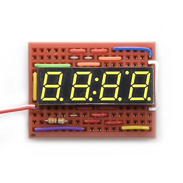
Why do people lay the wires on breadboards so tightly? Is that so they stay in and don't fall out as easily? It's bugging me... makes me feel as if I do it wrong...
It looks like they're precut jumpers.
So others can tell how its wired up by looking at it. Messy wiring jobs are harder to troubleshoot and generate schematics from. Thats why I generally do it.
I don't think its to keep the wires from falling out, correct gauge wire should hold well in a breadboard. It also might be due to obsessive compulsions, notice the blue wire at the top right corner of the image is bent at the right as it was slightly longer than needed!
I just bought the 14 pin one before the new 16 pin one came out. What datasheet do i read?????
Here's a link to the datasheet it sounds like you'll need: http://www.sparkfun.com/datasheets/Components/C4727JS.pdf. Sorry that info isn't more prevalent.
So, it turns out the pin-out in the datasheet is incorrect. The correct pin-out is now posted on the product page. Sorry about that!
that's a shame, but thanks for clearing that up for us. one last question is the display common anode like in the datasheet? or is it common cathode?
nevermind it says that in the 2nd line, i just didn't notice it :D
so to clarify, this is an almost identical product to the yellow one you used to sell, except it has a different pin layout? and a different amount of pins?
That's correct, Greeg. Both displays are the exact same size. The footprints are similar (same pin-spacing), however this display has all 16-pins connected (and a function for each pin), rather than the 14 on the older display.
Jimb0: That's correct, Greeg. Both displays are the exact same size. The footprints are similar (same pin-spacing), however this display has all 16-pins connected (and a function for each pin), rather than the 14 on the older display.
If so, what are the functions for pins 14 to 16? Datasheet only covers pins 1 to 13.
I read that go the datasheet too. I'm hoping that those pins (14,15,16) are N/C's because in my design i'll need to cut them off, i'm just wanting to confirm before i send off my board designs.