KTA-223 USB/RS485 Relay IO Board
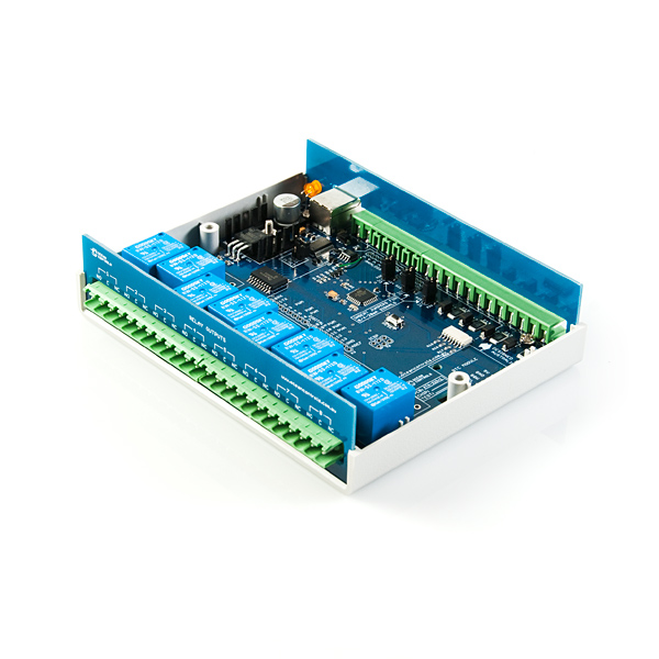
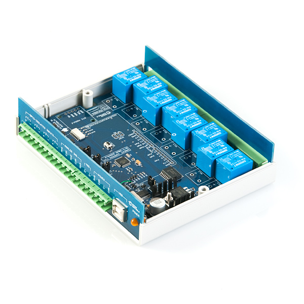
The KTA-223 Relay Board is a USB or RS485 controlled module that can interface a PC to eight or more SPDT relays. This could be very useful for controlling real world devices - such as lights and sprinkler systems - and reading sensors or monitoring switches and other digital signals.
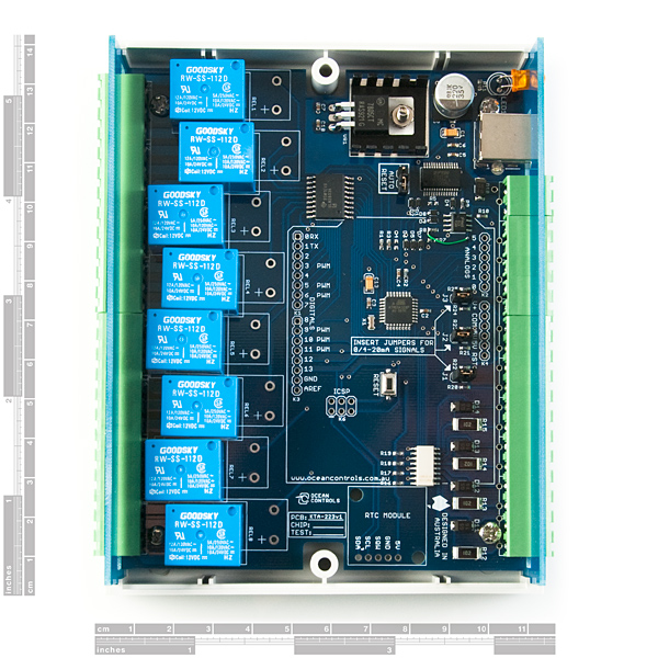
The controller is based on the hardware of the extremely popular Arduino platform. It can be programmed as a stand-alone controller using the free, open source Arduino environment. Internally, the controller is “shield-compatible”, allowing the use of many extension boards designed for the Arduino Deumilanove.
The on-board relays are capable of switching up to 5A at 250VAC, 10A at 120VAC and 10A at 24VDC, but the PCB traces can only handle up to about 5A.
With the default firmware, a simple ASCII protocol allows control from Windows/Mac/Linux using either USB Virtual COM drivers or RS485. Additionally, multiple devices can be connected to one RS485 bus, allowing control of many devices from one USB port.
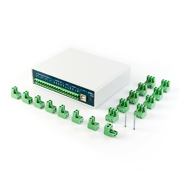
A large number of mating screw terminals are included with this product. USB cable not included.
Note: To get this to work with the R3 version of the Arduino Ethernet shield you will need to connect Pin 1 of the ICSP header to D12, Pin 3 to D13 and Pin4 to D11.
- 8 Relay Outputs 5A 250VAC
- 4 Opto-Isolated Inputs 5-30VDC
- 3 Analog Inputs (10 bit)
- Connections via Pluggable Screw Terminals
- 0-5V or 0-20mA Analog Inputs, Jumper Selectable
- 5A Relay Switching
- Power Indicator LED
- All enclosed in Professional looking plastic case
- Arduino Compatible
- Accepts Arduino Shields (Ethernet / XBee)
- USB Virtual COM or RS485 Input
- Easily connect multiple units far apart by RS485
- Updated firmware - fixes a bug with the Relay Status command (status of wrong relay was reported)
- User's Manual
- Schematic
- Product Page
- VB2k8 Test Software and Source
- VB6 Test Software and Source
- Delphi Light Flasher Software and Source
- Example Arduino ASCII Slave Sketch
- Example I2C firmware - allows the use of a RTC module with the relay unit
KTA-223 USB/RS485 Relay IO Board Product Help and Resources
Core Skill: DIY
Whether it's for assembling a kit, hacking an enclosure, or creating your own parts; the DIY skill is all about knowing how to use tools and the techniques associated with them.
Skill Level: Noob - Basic assembly is required. You may need to provide your own basic tools like a screwdriver, hammer or scissors. Power tools or custom parts are not required. Instructions will be included and easy to follow. Sewing may be required, but only with included patterns.
See all skill levels
Core Skill: Programming
If a board needs code or communicates somehow, you're going to need to know how to program or interface with it. The programming skill is all about communication and code.
Skill Level: Rookie - You will need a better fundamental understand of what code is, and how it works. You will be using beginner-level software and development tools like Arduino. You will be dealing directly with code, but numerous examples and libraries are available. Sensors or shields will communicate with serial or TTL.
See all skill levels
Core Skill: Electrical Prototyping
If it requires power, you need to know how much, what all the pins do, and how to hook it up. You may need to reference datasheets, schematics, and know the ins and outs of electronics.
Skill Level: Competent - You will be required to reference a datasheet or schematic to know how to use a component. Your knowledge of a datasheet will only require basic features like power requirements, pinouts, or communications type. Also, you may need a power supply that?s greater than 12V or more than 1A worth of current.
See all skill levels
Comments
Looking for answers to technical questions?
We welcome your comments and suggestions below. However, if you are looking for solutions to technical questions please see our Technical Assistance page.
Customer Reviews
5 out of 5
Based on 1 ratings:
Very useful for any electronics lab or manufacturing facility
This is a great little device to have around for automating all sorts of things: from quickly building manufacturing test rigs to one off lab tests.
With schematics, source code and a well written manual online I wrote my code while waiting for it to arrive. Configured their addresses and everything just worked without any issue.
The fact that they can be daisy chained via RS-485 is a great plus for larger setups. The only concern I would have is that there is no hardware flow control employed so it is important that host software properly pace command sequences. However at 9600bps it seems to operate reliably.


I've taken the VB.NET test software (in the Documents section above) and converted it into C#. You can access it here: KTA233 Tester
I should have read the manual closer before ordering, but under the using the controller section of the manual I understood that line, "The controller requires 12VDC or 24VDC to operate" to mean that it could take either voltage as the input voltage. Anyway, for people like me who apparently can't read, there are two models with separate input voltage ranges. Sparkfun sells the 9-16VDC model, and I think it would be nice to see that specification added somewhere in the features list or description. I luckily caught my mistake before creating smoke, but the board just became really inconvenient for me to use.
The latest version of the KTA-233 now accepts a wider range of input voltage, from 6.5 to 36 V (see owner's manual on Ocean Control's website).
I built an Android App for the KTA-223 and put it on Google Play. The app can be found here. All you need is an OTG cable. More features coming in the coming weeks.
can somebody explain to me why there are 2 555 timer in the circuit? they are shown on sheet 4 on the schematic.
According to the GoodSky datasheet the RW relays used aren't rated for 230V, only 120V. For 230V operation the RWH type is required.
SFE, could you please update the description?
Wondering if anyone has actually gotten the RTC module to work with this? The linked example code above doesn't seem to work. I've got a forum topic open here for feedback... Thanks.
Check out this tutorial on using this with a WiFi shield and a couple of other SFE bits to get internet controlled relays.
Does any one know if it's possible to add wire in parallel to the board trace to increase the current rating of the relays?
Can you check the link "Example I2C firmware" ? It doesn't work for me.
FYI I just finished building a project that uses this product in combination with the wixel arduino shield and 2 wixels. Pressing buttons in one location causes one standalone wixel to send the wixel that's stuck to this relay box (via the shield) a message via RF. The receiving wixel sends a serial message to the relay box saying which relay to turn on/off. Works like a charm. I thought I'd have to do some wixel programming and some arduino, but it turns out it only needed wixel stuff. I'll be posting info on the project, along with the wixel app soon. Just thought I'd let people know that it's possible. Only issue is that the case doesn't fit back on the relay box, since the wixel sticks up too high.
Worked as an adruino for a day, then I would not allow upload? Any Ideas?
Have you tried to re-flash the bootloader on the ATmega328p via the ISP/ICSP connector labeled K6?
Jeff Baron:
The documentation for this module "recommends" the connection of simple electronic circuitry of various forms to the outputs of the relays in order to protect the unit from voltage spikes from large inductive loads.<br />
<br />
It looks - from the pictures - like the relay outputs are wired to connections inside of the unit (as well as to the normal outside connections) in order to facilitate the installation of the capacitors, resistors, and diodes inside of the unit.<br />
<br />
Is this the case? Thanks.
This seems like it would be perfect for making environmental controls for a vivarium/terrarium.. (temp and humidity sensors, light and mister controls).