ePIR
Replacement: None. We are no longer carrying the ePIR in our catalog. This page is for reference only.
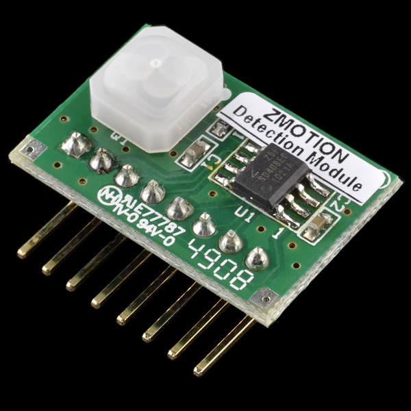
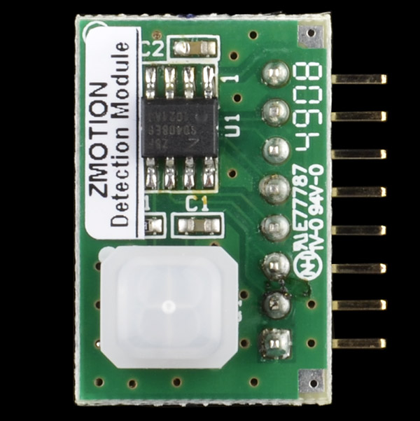
Zilog's ePIR is a fully functional motion-detecting single-board computer (SBC). Combined on this board are a Z8 Encore! XP MCU, and a Murata passive infrared (PIR) sensor, which is shielded by a Fresnel lens. Taking advantage of the processing capabilities of the Z8 MCU, the ePIR uses a powerful new statistical processing method to provide exceptional motion detection performance.
The ePIR provides two interface modes: a simple hardware interface and more advanced serial method. If you're using the hardware interface, the motion detect (MD) pin will go low when motion is detected. In serial mode, the ePIR is read and configured using the defined set of commands - all sent asynchronously at 9600 baud (8-N-1).
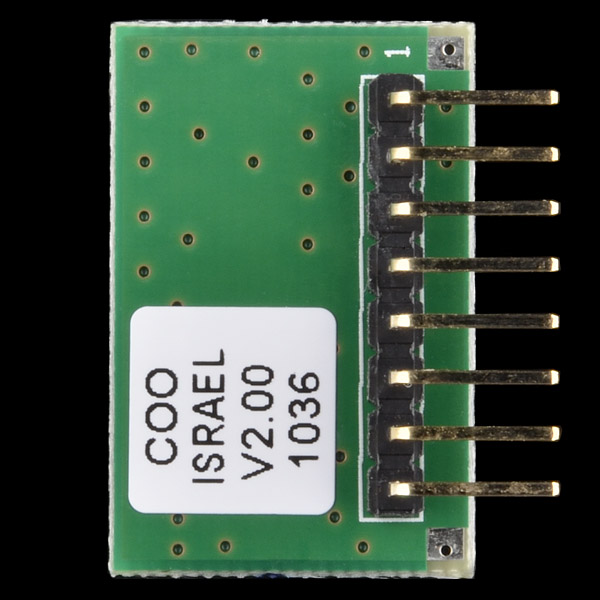
The physcial interface of the ePIR is an 8-pin, 0.1" pitch male header.
- Complete, fully functional motion detection SBC including low profile Fresnel lens
- Advanced software based motion detection algorithms provide superior sensitivity and stability
- 2.7-3.6VDC operating voltage
- Typical current draw: 8.9mA
- Wide 5 x 5m, 60 degree detection pattern
- Simple hardware or advanced serial (UART) based configuration and interface
- Adjustable sensitivity, delay and ambient light threshold
- SLEEP mode for low power applications
- No temperature compensation required
- Dynamic PIR sensor stabilization minimizes power-on time
- Photocell input for ambient light detection in lighting applications
- Minimal components ensure highest possible Mean Time Between Failure (MTBF)
- Production ready solution or develop your own custom software application
- Complete development system available (ZEPIR000101ZCOG)
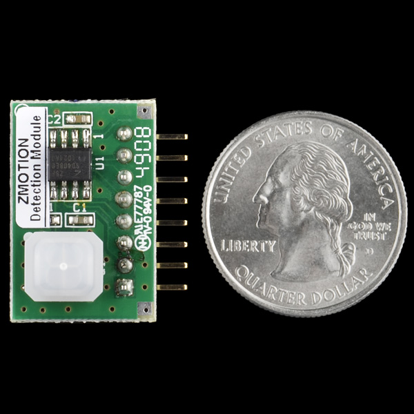
- 25.5 x 16.7 mm
Comments
Looking for answers to technical questions?
We welcome your comments and suggestions below. However, if you are looking for solutions to technical questions please see our Technical Assistance page.
Customer Reviews
No reviews yet.


Has anyone compared the sensitivity of these ePIR modules to that of the 'regular' PIR module like SEN-08630?
Could SFE run a test in the same spirit as the RF module range experiments?
Here's a small comparison video I did: PIR Sensor Comparison
just wondering if there is an eagles file for this
you can simply use a 8pin header wit .1" pitch.
use the M08 in the SFE library
Good call, worked great thanx!
I have a few of these sensors and they work fine. I haven't tested range, but the datasheet seems reasonably accurate. While they do have a digital mode, the analog mode is much similar to use when a simple, static configuration is desired. Essentially with some trimpots or static voltage dividers, you can set the sensitivity and activation duration and connect this to a uC GPIO input to detect motion. The example circuit works perfectly with a few resistors and an LED.
+1
Any additional information on this little guy would be much appreciated.
Hello, I´m having some weird problems with this sensor in hardware mode. If I test it in a protoboard, connecting pins 1,8,3, 4 to the ground, pins 2, 6, 7 to Vcc(3v) and pin5 to a voltimeter. It works very fine. But I designed a printed circuit board with the same layout using a "Kit - EZ430-RF2480" 8 (a MSP430F2274 kit from TexasInstruments) as "brain". But whenever I connect it the pin P2.3 of the uC, the pin 5 starts just sending "0 1 0 1 0 1 0 1..." , the rest of the pins are high or low as described (with the same Vcc and ground as the uC). I have activated the ADC module in this pin, so it recognize when when pin is high or low (I know it not the best way... but it should work). Working as ADC, it wouldnt matter if by accident I put HIGH or LOW this pin, so I just dont know what is happening :/ ¿Someone could give me some light? Many thanks in advance.
Anyone have any recommendations for permanent mounting of these? I'm trying to get them to face away from the circuit board, but since they are mounted on 90 degree headers I can't seem to get it quite right. I tried male 90 degree breakaway headers, but I'd need a female-to-femal .1" spacing set of connectors to get that to work.
Any help? Anyone solved the mounting problem??
Thanks!
Use pliers to bend the header around 90 degrees so it faces away from the board. Or you could just desolder the whole header and solder in a new straight header or wires
I'm having problems connecting this to a picaxe 08m2. I followed the pinout with the propeller information mentioned. Does anyone have the correct pinout for a picaxe 08m2? It appears that i'm not getting any motion detection. i have several of them and switch a few out to eliminate hardware problem. And I have checked the wiring over and over. Any help is appreciated. Thx, in advance.
I have one of these connected to an RPi and I am having issues with it being way too sensitive. I keep getting false-positives (motion sensor detects motion when nothing has changed). I have it connected to serial and so I have the sensitivity at the highest value, 255 (least sensitive according to the Datasheet). User ThomasFletcher who commented on here is having the same issue.
Has anyone else fixed the issue about over-sensitivity?
Hi, I got this sensor before and it was perfectly working. Got two more recently and they seems to be programmed differently.
I connected the ePIR module to an RS232 and checked the pin5 config, it's in Reset and not MD mode by default. I can change the config to MD while I am connected to the RS232, but as soon as I reboot the ePIR module the config goes back to Reset on pin5.
How can I save the config ? Can not find anything specific about that in the manual.
Thanks for any advice.
For extra info check out the Aplication notes from the Product Page. It's very helpful.
http://www.zilog.com/docs/appnotes/AN0307.pdf
Would this device be able to detect eyelid/eyebrow movement?
For a complete Arduino based burglar/ fire alarm system which could respond to this sensor, see...
http://sheepdogguides.com/arduino/aht8lokb16.htm
Note that it has the necessary "Wait for sensors to stabilize" code, among other things
How to wiring for digital mode with arduino uno?
any chance of sparkfun getting just the Z8? I've been looking for something just like it.
I've wired up this sensor using the datasheet circuit for "hardware interface" mode hoping to trigger a relay to turn on a lamp. Everything's fine except somehow I have a normally HIGH signal (lights up the debug LED)) that goes LOW when it detects movement. I think the datasheet says it runs in an active low state. Anyone else?
If this is correct, is there a relay that will open under current and close when the pin goes LOW?
Alarm systems are normally closed circuits. If they were normally open you could cut a sensor cable and get away with it (circuit would never go high/closed).
I guess that is the reason for the always HIGH state of the pin.
Will the stock levels be going up any time soon?
I dont want to design a product around this board to find it's not available for a period of time.
Anyone knows what is the S/W Revision for this? 1.0 or 2.0?
The current ones are v1.0, but our next batch will be 2.0. There are only very minor changes accrording to the manufacturer.
I bought a few of this and work fine! But, is there a way of changing the character stent in serial mode? Or, is there a way of telling appart two sensors conected to the same serial port? Thanks!
The link for the datasheet is broken....
Try it again, they all work for us.
Yeah the link is malformed
the link has http:/// and not http://
I still get "The address is not valid" message. But I was able to get it from the Zilog site.
HOWEVER there is an error in the datasheet (document PS0284) concerning pin 6 (the LG pin). In the text that describes the operation of this pin (on page 6) it states that if voltage on this pin is lower than 1V then the MD signal will NOT activate (which is accurate). However, in the summary below this text it says the opposite.
Just got one in and I am not sure about the wiring to a propeller prop. It is working to recognize motion but I am getting a lot of false hits when there is no motion.<br />
<br />
I have pin 5 going to a prop pin that I have set for input. Program checks for when the pin goes low to indicate something tripped the sensor.<br />
<br />
I got pins 1,3,4,8 going to ground<br />
<br />
And pins 2 and 6 going to 3.3V<br />
<br />
<br />
Am I doing something wrong?
I think you forgot the pin 7 to wake up the module. (SLEEP MODE = pin 7 to GND or unconnected)
Good operation in HW mode for the default range, nice low voltage operation. However, running some crude tests, the "extended" range (only available in serial mode) on these did not appear noticeably better than the default range (~3m). In addition, there was an issue with the delay setting in serial mode (or digital mode as an earlier poster referred to it). When the MD/RST pin is set for MD (using serial command "CM") it stays active (low) for about 40 seconds ignoring my delay setting of two seconds (serial command "D2").