Triple Axis Accelerometer Breakout - BMA180
Replacement: None. We're not carrying this part anymore, but check out the rest of our accelerometer category. This page is for reference only.
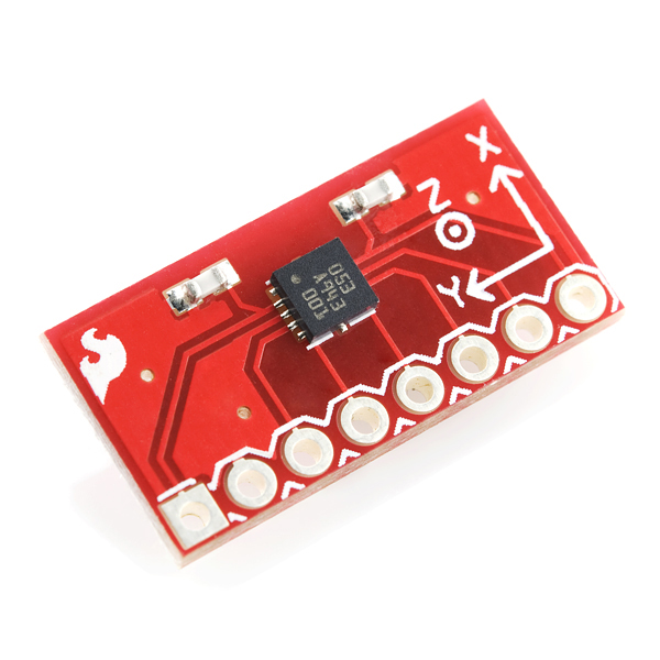
This is a breakout board for Bosch's BMA180 three-axis, ultra-high performance digital accelerometer. The BMA180 provides a digital 14-bit output signal via a 4-wire SPI or I2C interface. The full-scale measurement range can be set to ±1g, 1.5g, 2g, 3g, 4g, 8g or 16g. Other features include programmable wake-up, low-g and high-g detection, tap sensing, slope detection, and self-test capability. The sensor also has two operating modes: low-noise and low-power.
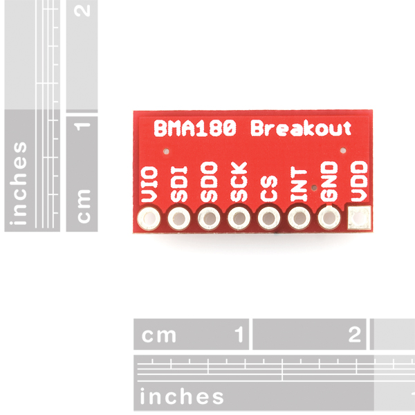
This breadboard friendly board breaks out every pin of the BMA180 to an 8-pin, 0.1" pitch header. The board doesn't have any on-board regulation, so the provided voltage should be between 1.62 and 3.6V for VDD and 1.2 to 3.6V for VDDIO. The sensor will typically only consume 650uA in standard mode.
Not sure which accelerometer is right for you? Our Accelerometer and Gyro Buying Guide might help!
- Wide variety of measurment ranges (±1g, 1.5g, 2g, 3g, 4g, 8g and 16g)
- 14- or 12-bit ADC conversion
- 2 selectable I2C addresses
- Programmable integrated digital filters (no external components necessary)
- 8 low-pass filters
- 1 high-pass filter
- 1 band-pass filter
- Programmable interrupt features:
- Wake-up
- Low-g detection
- High-g detection
- Tap sensing
- Slope detection
- 2 main standard modes: low-noise and low-power
- Sleep mode
- Wake-up mode
- Self-test capability
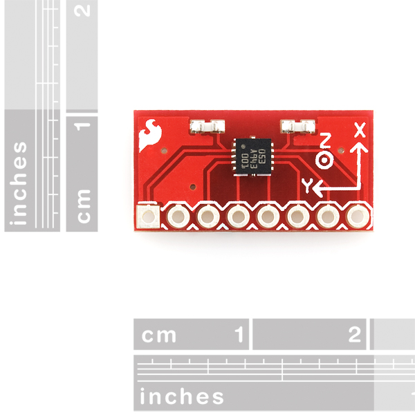
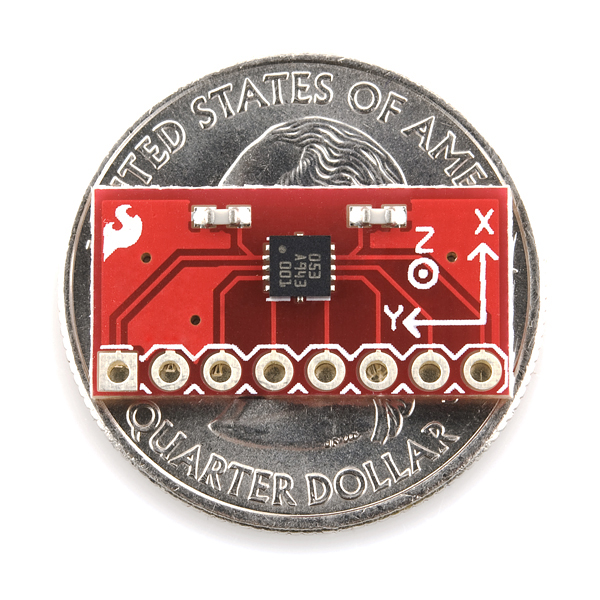
- 0.80 x 0.40"
- Schematic
- Eagle Files
- Datasheet
- Example Code (ATmega328)
Comments
Looking for answers to technical questions?
We welcome your comments and suggestions below. However, if you are looking for solutions to technical questions please see our Technical Assistance page.
Customer Reviews
No reviews yet.


I am using the BMA180 with an Arduino Min Pro 3V3 and SPI communications.
I found that I had to use SPI Mode 0 (CPOL =0, CPHA = 0), whereas the Bosch Data Sheet implies that Mode 2 (CPOL = 1, CPHA = 0) is required.
At first I thought it might be clock frequency/connection related but I tried at both clock rate extremes and it works fine with Mode 0 but not Mode 2.
Any similar experiences; I want to understand whether the data sheet is wrong or something else is going on here.
I found that Phase = 1 and Pole = 1 works fine. I think the datasheet indicates that sample is on rising clk and clk is normally high.
This was a great accelerometer because it is very sensitive at 1g. I cannot find a replacement that has this sensitivity. Does anyone know of one? Thanks.
This was a great accelerometer because it is very sensitive at 1g. I cannot find a replacement that has this sensitivity. Does anyone know of one? Thanks.
It seems as though I can't change the range on this thing. I write to the reg and then read it back and I can see that it accepted the write but the ADC values are the same. When the sensor is oriented with the +Z pointing up it reads about 1800 on the Z axis and 500 on the X and Y. It doesn't make much sense to me. I looked at several other's code and I'm writing to the same registers in the same order as all the examples I found. I found one other post mentioning the same issue.
Anyone have any sample code using Python to convert the values to something usable?
Hello people, I´ve been testing this sensor for a while and I still can´t change the acceleration range. I can change the register 0x35 with the data I need but the eeprom is always in the default value after a soft reset. Anyone has any idea please? Thank you very much!
Hello people, I´ve been testing this sensor for a while and I still can´t change the acceleration range. I can change the register 0x35 with the data I need but the eeprom is always in the default value after a soft reset. Anyone has any idea please? Thank you very much!
I have 2 BMA180 connected to an arduino on a adafruit datalogger shield (there are onboard i2c pullups) using long cable to each (4m) into the i2c bus. I came across with a strange problem. I am reading the values every 25ms in block of 7 bytes using the BMA180 library from here http://www.varesano.net/files/libraries_20120118_0959.zip. In the beginning the capturing is ok 8g mode ACC1_X ACC1_Y ACC1_Z ACC2_X ACC2_Y ACC2_Z 2 -45 1195 147 -128 1345 4 -55 1174 149 -124 1406 -3 -42 1209 144 -130 1336
but after some time things go really strange and the sensor is still
later
the strange "offsets" happen all the time. Its like the value off the Z is moving to the other values.
here is plot with the problem Its a 1h log.
Any ideas?
Yo Sparkfun! Accelerometers can't accurately measure movement unless they are rigidly connected to the thing that is moving. Please put mounting holes on all accel breakout boards! Preferably 4 of them so the accel is not cantilevered!
If you plan on using BMA180 with SPI, there is possibility of collision between SPI and I2C. It can be taken care of, though. See this thread.
Is it possible to use this device with a Arduino Uno? Is it necessary to use a logic level converter?
Mine works fine with my Arduino Uno. I have not had any problems using it on a 5v supply. It also works if you power it from the 3.3v supply. The digital in/out will work just fine with 3v even through they are expecting 5v.
Like others, I've been dealing with the apparent i2c address discrepancy with this part. The data sheet says 0x40 and many are finding that 0x80 is what works. The problem is that when Bosch lists 0x40, they are actually only referring to the 7 MSB's of the i2c address. So, if your system (like mine) wants you to specify an 8 bit address for the part, it is in-fact 0x80. I believe the Arduino wire library may only want the 7 bit address, so what Bosch lists works for Arduino. I confirmed by looking at Arduino i2c transactions with a logic analyzer. I've only looked at a handful of data sheets for i2c sensors, but the BMA180 isn't one of the stellar ones.
I'm having trouble setting BMA180 registers (eg, the range and bandwidth registers at 0x35 and 0x20) using a UBW32 PIC32 board.
I can read the version, gain, range, and acceleration values alright (using SPI with control byte with leading bit 1) but after writing (control byte with leading bit 0), a read returns the same value the register had before the write. I'm writing directly into the setting register, not the EEPROM register -- the data sheet says this is read/write, but I can't get the write to work.
Any pointers on what I might be doing wrong will be appreciated; thanks in advance.
Ok, I got it -- need to set the ctrl_reg0 ee_w bit. With that set the image registers change properly.
ummm quick question... I'm working on my thesis right now... And I'd like to use some of the pictures here (for example this BMA180)
am I allowed to?
EDIT: I got my answer :) thank you!
I am trying to communicate with the BMA180 with SPI. Is there any command I can send that will return a known output so that I can know if I am data correctly.
Is it right that you send a 1 followed by 7 bits which are the register number that you want to read?
How about the version and chip ID registers? They won't change whereas other ones will.
May the measurement range be changed on the fly? say as part of the program?
When will this product be in stock again?
i have sucessfully tried the example code .....
how to set bma180 so the chip will send 100data every second?
i'm using bma180 with atmega328 on 16mhz ...
i've compiled and build the makefile with F_CPU=16000000
do you know what is the setting for hyperterminal?
i use 9600bps,8bit,no parity,stopbit1,dataflowcontrol none.
i also try with 19200bps but the uart wont show on hyperterminal ...
btw i want to set hyperterminal on 9600bps,8bit,no parity,stopbit1,dataflowcontrol none.
what is the uart initialization code for main.c ? (i'm using winavr) . thank you ...
Mine returns version 0x14.
SPI modes 0 and 3 work for me (so I'll use mode 3 so SCK is high when idle, see datasheet).
-
Thanks MUX, mine had the same problem, the address was 0x80 instead of 0x40 with SDO grounded.
I'm using a picaxe 18M2
Any one else got Version register to read out like 0x14 instead of 0x12 as stated in the data sheet. I don't have any problems just did got confused when I was trying to set it up.
For the people who speak Spanish.
Acabo de incorporar al proyecto Mikuadric0ptero El Acelerometro BMA-180
Si quer�is conocer mis comentarios y el C�digo para manejarlo. Os invito a visitar: https://sites.google.com/site/mikuadricoptero/home/descripciones/1-72-acelerometro-02
mine has the address 0x80 although the datasheet says that it should be 0x40 when SDO is connected to the ground, weird...
Anyway, mbed sample here if anyone's interested:
http://mbed.org/users/mux/programs/bma180/lhnw4q
Hooray! I was lucky placing an order with BO BMA180 Breakout and now I'll get one)))
Btw, support says they'll receive chips in 2-3 weeks, so be ready to catch it)
ARRRRGGGHHH!!!
No way! So little stock? I coudn't even order it when I saw the stock notification mail!
Are we going to wait another 1 or 2 months for the stocks to arrive again?
Any update on availability yet?
Hi, might anyone have a schematic to show connection of this accel sensor to an Uno and some Arduino example code ? Thanks!
My Quadrocopter is anxiously awaiting this board (well, me too :) ). Any update on the shipment of the IC yet? Thanks for any update.
Can we have an update on when/if this board will be back in stock?
It's hard to say, we are out of stock on the IC and awaiting shipment.
Feels like forever waiting for the boards to arrive.
Thanks for the update
Any idea when these will be back in stock?
I have the BMA180 breakout board going through a logic level converter into an Arduino Mini 04. I am able to communicate with the accelerometer and write changes to the registers but I have not been able to use the interrupt feature.
Has anyone had luck triggering interrupts with the BMA180? I am looking to trigger an interrupt on a double tap (any axis), I have set the necessary settings and threshold but I still cannot trigger the interrupt.
Insight?
Are there any SPI or I2C wiring examples for using this accelerometer with Duemilanove? The diagrams in the datasheet aren't working for me.
In case other people need to see the wiring diagram I used, take a look at http://www.centralnexus.com/seismograph/details_bma180.html
A logic level converter should not be used. It makes the readings very noisy.
you will also need a logic level translator for it to work with the arduino
SDO -> GND (VSS)
SDI -> A4
SCK -> A5
INT, CS, VIO not wired
Device Address of 0x40 (pg 54 of the datasheet describes address selection)
Is there a wiring setup to connect via I2C with PIC18F?
http://www.sparkfun.com/datasheets/Sensors/Accelerometer/BST-BMA180-DS000-03.pdf
Hello, is there any way to interface BMA180 with a pic microcontroller? Does exist any example of code compatible with PIC mcus? Plz, i need answers its pressinggg!!!