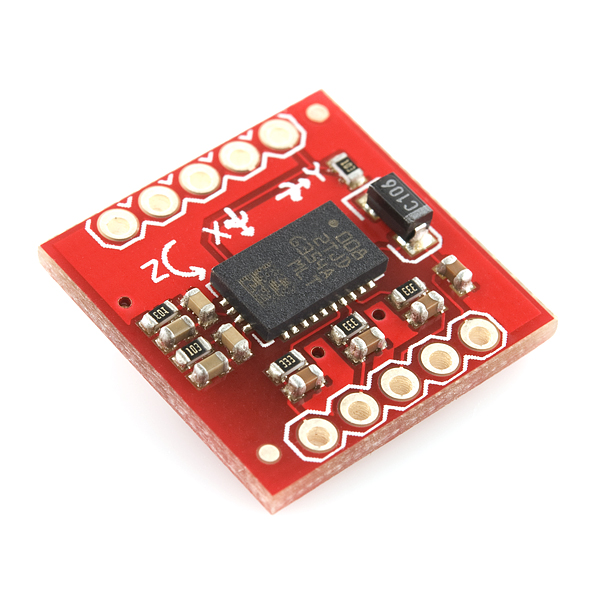
Triple Axis Gyro LYPR540AH Breakout
Replacement: None. The chip never shipped. These were gone before they were made. This never happened. Check out our gyro category for more gyro breakouts. This page is for reference only.
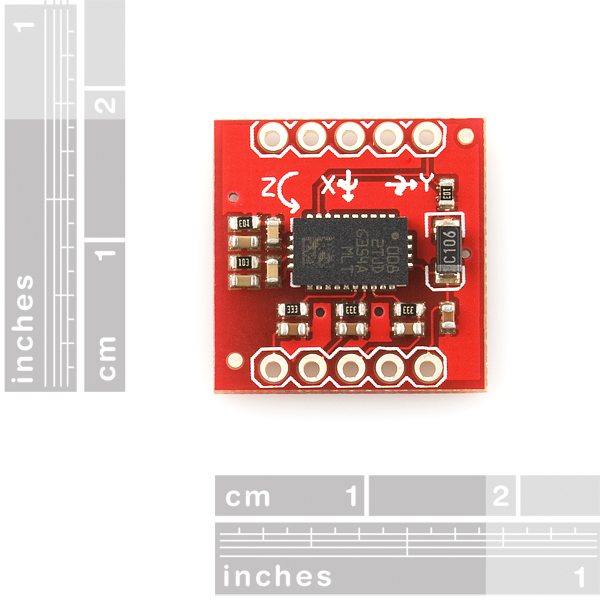
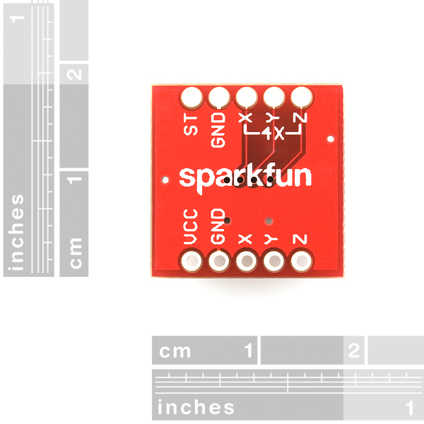
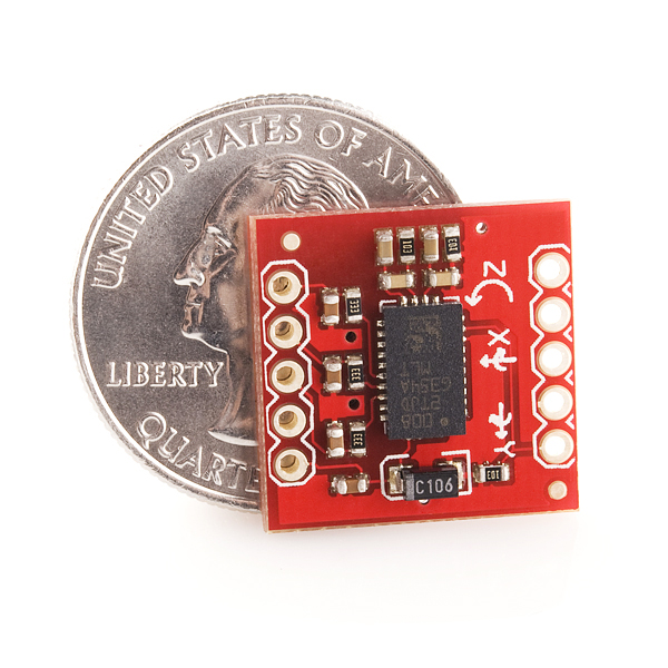
One of the first triple axis gyros we've seen on the market! This is what we love to do - a simple breakout board for the triax LYPR540AH gyroscope, tested, and ready to go. Both 400dps and 1600dps outputs are brought out for all three channels.
This board has an on-board 10k pull-down resistor to keep the gyro out of self test mode. You will normally attach to 5 wires: VCC/GND and 3 analog outputs (X/Y/Z), but the 4x amplified outputs are also available.
Not sure which gyro is right for you? Our Accelerometer and Gyro Buying Guide might help!
- 2.7 to 3.6V supply
- 1600 degree (max) per second outputs
- 400 degree (max) per second 4x amplified outputs
- Self test pin
- -3dB bandwidth @ 140Hz
- LYPR540AH Datasheet
- Schematic
-
Anyone else notice that ST has a typo on their datasheet - 'indipendant'? Glad we're not the only ones with bad speling.
Comments
Looking for answers to technical questions?
We welcome your comments and suggestions below. However, if you are looking for solutions to technical questions please see our Technical Assistance page.
Customer Reviews
No reviews yet.


LYPR540AH provides amplified (?400 dps full
scale) and not amplified (?1600 dps full scale)
outputs for each sensible axis available at the
same time through dedicated pins
I think the DPS for 4x amplified & non-amplified outputs are interchanged in the FEATURES !!
should be
Features:
2.7 to 3.6V supply
1600 degree per second outputs
400 degree per second 4x amplified outputs
Self test pin
-3dB bandwidth @ 140Hz
My mistake. Fixed now. Thanks!
I agree, as this method is how all other gyroscopes on the SFE site are amplified.
still waiting for it.....
When the LYPR540AH product is restocked?
i have connected LPY5150 Breakout board like this:
Vcc----------->3.3 volts
GND---------->Gnd
ST,PD,HP----->gnd
1x---------->Not connected
outputs 4x-->Connected to analog pins of PIC16F877A
vref-------->connected to analog pin of PIC
iam reading three values 4x- X,Z and Vref.
hello all..
Iam using LPY5150AL Breakout gyro. I have connected to a PIC16F877A microcontroller.The problem is that iam getting outputs of gyro around 1100 -1300 deg/sec when i rotate the axes.I donot know whether these values are correct are not??can anyone help me out..!
The formula used is:
X_deg=((V_out-V_reference)*5000/1024)/(sensitivity)
where v_ref=1.23 as suggested in datasheet.
THANKS ALOT..!
This part is now listed on their site as "NRND" or: Not recommended for new designs.
Sounds to me like with all these delays, they may have decided it was just a bad design and scrapped it.
Though mouser has a demo board available for $25.
ST sent me 5 of these when I asked for samples. And I only asked for 2 or 3! Took about a month or more though.
If you guys need some, just ask them!
I STILL haven't had time to try mine though! Next week hopefully...
-Taylor
Hey, I'd really like to have one of those little gyros, since ST seems to have stopped handling evaluation requestes... :(
The problem is that I'm not in US, but maybe we can find a solution?
Regards,
Costa
Where are you located?
-Taylor
Bucharest/Romania... Eastern Europe ;)
Do you have a board for it?
Send me an e-mail. :)
Its my username here @gmail.com
-Taylor
If you go to the barebones arduino board site modern devices...
Home > Modern Device > Sensors > 3-Axis Accelerometer Module
they have 3 axis acselerometer... ask a librarian and they will twitch till it is found... :)
3 axis accelerometers have been around for a while, but this is a 3 axis rate gyro, which is different, and new.
I wonder what is the resonant freq of the sensing element. Will it suffer the same issue as the LISY300AL where vibration from the motor will cause serious interference to the gyro?
From the data sheet, the amplified outputs give the 400 degree / second output and the non amplified outputs are for the 1600 degree / second output.
The data sheet has contradicts it's self. The first section is backwards from the second.