So a curl of smoke is rising from the last solder joint in your new project, and after months of planning, designing, ordering and building (or perhaps just putting a kit together), you're finally ready to power it up. Should you just hook it up to a battery or the mains and throw the switch? Whoa there, Turbo! 1 They call this "the smoke test" for a reason, but you can minimize your chances of setting off the smoke detector (and losing your street cred) by taking it slow and remembering a few simple tips. Most of these tips are geared towards PCBs (Printed Circuit Boards), but many of them can be applied to breadboarded circuits as well. Let's heat 'em up!
First, take a break (or at least a breath). A reboot can help you see problems you may have missed before. Then, visually check your work. Do unpopulated footprints suggest a missing component? Are any parts left over? (Protip: counting out only the needed parts beforehand can help eliminate leftovers. An old Heathkit technique (get off my lawn!) is to use an egg carton to keep everything organized.) This is also a good time to double-check part values. Are the right resistors in the right places? Are your polarized capacitors, diodes, and LEDs installed in the correct direction? You'd be surprised how often this happens, even to us "professional" 2 engineers.
While you're scrutinizing your work, look for solder bridges, especially between the pins of fine-pitch SMD chips (but note that adjacent ground pins will often bridge to each other; it may look alarming, but isn't a problem.) Finding and fixing solder bridges now, before they blow something up, can save you from having to order new parts. (As much as we love you as a customer, we love your success even more.)
While you're at it, keep an eye out for solder balls (which is also a good curse to use around the lab). These form when flux boils underneath liquid solder, causing it to spatter. They have a nasty habit of getting lodged between IC pins, causing intermittent and hard to diagnose problems later.
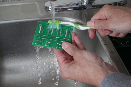
I know it delays gratification, but something I like to do at this point is to clean the flux off the board. If your board doesn't contain any moisture-sensitive components (barometric and humidity sensors come to mind), and you've been using water-soluble flux (other types of flux require alcohol or other solvents), then take an old toothbrush, a drop of detergent, and give the board a quick scrub under some warm water. Give all the solder joints and surrounding surfaces a good brushing, and rinse well afterwards. (Protip: when you're done, don't leave your board-cleaning toothbrush by the bathroom sink.)
You won't want to do anything further until the board is absolutely dry. I'm never patient enough to let it air-dry, so I'll use a heat gun (on low) or even a hair dryer on the board until all the visible water has evaporated, and then give it an extra minute to make sure all the hidden water is gone. Technically you don't have to clean most types of flux off your boards. Most circuitry will work fine with the flux left in place. However I've seen this step miraculously fix malfunctioning boards by getting rid of hard-to-see solder balls, and removing the flux can make sensitive analog circuitry work better. Plus, cleaning your board makes it look spectacular.
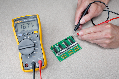
Now are we ready to apply power? Not yet. Repeat after me: when in doubt, ohm it out. Before applying power, use a multimeter to measure the resistance (not continuity) across the power input to your board. Hopefully you'll see above 10k and even above 1M ohms of resistance. That much resistance means there aren't any shorts upstream of your regulator (if you have one), which is a good thing. (It's OK if the resistance is changing, this is from the multimeter weakly charging the capacitors in your circuit.) If your circuit has any voltage regulators in it, this is also a good test to run downstream of them. Check the resistance between each regulator's output and ground; you should see a high resistance as described above.
If you ever see only a few ohms, that's a short, which is trouble waiting to happen (but won't because you caught it in time!). Shorts are most often caused by solder bridges, but they can also be caused by putting a part in the wrong place. Carefully check your circuit, comparing it to the schematic. When you've found and fixed the short, check the resistance again to verify that you're no longer in the danger zone.
Occasionally you'll reach a point where everything looks correct, but the short stubbornly remains. Before throwing your board out the window (not recommended for orbital or underground lairs), remember that the fault could be from a bad part, or it could be on the PCB itself. It's rare for a part to "fail shorted" (more often they'll "fail open"), but it can happen, especially with MOSFETs. And they're rare, but we do see PCB errors from time to time.
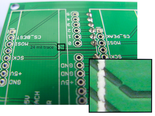
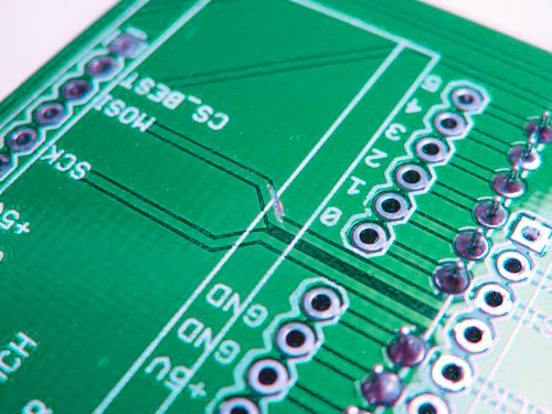
Both of these problems can be very hard to track down. The trick is to divide and conquer. Be ready to cut traces (you can repair them later) and remove parts to zero in on the problem. PCB errors will almost always be a hairline copper bridge from a trace to the surrounding ground pour. Once you find it (a bright light and magnifier will help), breathe a sigh of relief, curse your boardhouse, and use a hobby knife to cut the offending whisker.
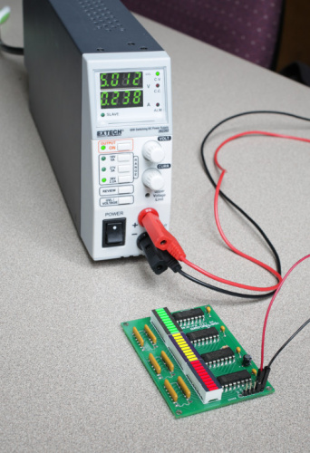
We're almost there! If you have one, this is an excellent time to use a benchtop power supply with current limiting. Before connecting the power supply to your circuit, set the supply's voltage to what your circuit requires, and set the current to be a bit more than what you're expecting your circuit to draw. This way, if your circuit does decide to draw a bunch of current if left to its own devices (ha!), the power supply will drop the voltage to keep the current at the value you set, often while turning on a helpful red LED.
It's finally time for the smoke test! Connect your circuit to the power supply, turn on the supply's output, and see what happens. Because of all the steps you performed above, this should be pleasantly uneventful. Hopefully your circuit powered up correctly, and your power supply didn't complain. You may now do the Snoopy dance if you wish.
If your circuit isn't working the way you expected it to, do some spot checks with your meter while it's powered to make sure the right voltages are where you expect them to be. You might also want to remove power and start checking for the opposite of shorts; open circuits, AKA things that should be connected but aren't. This time, set your meter to continuity, and start working your way through the schematic, verifying all the connections. (A paper schematic is helpful here, as you can cross off the nets as you check them.) If you don't hear the "beep", you'll know something's... asleep? (We'll work on that.)
Now that your circuit is (hopefully) up and running, you can test the functionality. This is where you'll start putting code on a microcontroller (we've all forgotten this step once... or twice), and/or attaching inputs to your circuit and verifying that the outputs are what you expect them to be. A good tip here is to start simple, and work your way up to full functionality. If something's not working, figure out why, and hack it until it's right. Congratulations! You did it!
One last thing. Even as you're basking in the well-deserved glow of your achievement, you probably noticed some design problems or other areas that could be improved upon. This is a great time to write down lessons learned; things that you can review before your next design that will help make your projects better and better.
All of us (except Pete) started out knowing nothing. The way we get good at this stuff is pressing forward, making mistakes, remembering not to make those particular mistakes again, and making all-new mistakes next time. There was a point to this story, but I seem to have forgotten it.
We hope this has been helpful! If you have any tips or rituals you use when powering up your projects for the first time, let us know in the comments. Also, if you have a better name for this series than "Engineer Thursday", let us know. Please.
1. You can thank Dave for this classic SparkFun 404 message.
2. A special effects artist named Greg Jein once said that it was personally important to him to always remain an amateur, since the label "professional" can imply that you are done learning. Amateurs are willing to try new things because they haven't been told that's not the way it's done; this idea is at the core of the maker movement, and something we embrace at SparkFun.



Thursgineering?
That does have a certain ring to it.
just stumbles off the tongue...
In the early science fiction pulps, before "electronics" was established, they had experts who were electronicists and other variations. Now I'm kind of liking "Thorgeneer" as an alternative to EE. I'll make a diploma and start awarding the Thorgeneering degree from some official sounding society if anyone wants one. Something along the lines of the Montgomery Burns Award for Outstanding Performance in the Field of Excellence. The Institute for Advanced Studies of Outstanding Performance in the Field of Thorgeneering? Get out the wide printer!
Electron Day!
Since Thursday is Thor's Day and the relation to lightning and sparks, "Thorsday" or "Engineering Thorsday". Well, someone come up with a better play on the Thor thing. My word play Fu is very Kung Fu (long time, slow) today. [ust for the heck of it, Monday = Moon, Tuesday =Tue=Mars, Wednesday = Woden's Day, Thursday, Friday = Friea's Day - wife of 'Oden, then Saturn and the Sun].
Excellent write up. When I was a young engineer we had a game going. When we worked at fixing a board (of known good design) we would ask if the problem could have been found by visual inspection. About 99% of the time, looking closely would have found the problem. Of course we DID look closely, sometimes just not close enough. ;-)
Another tip: For new (unproven) designs it is sometimes useful to add components a little at a time to bring up the board in sections. For instance, bring up the power supply portion of the board before adding the rest of the circuit. This can be complex. You have to know how each section interacts with the others (like the power supply might require a load to regulate), but if used correctly this can vastly simplify debugging a complex new design.
That's good advice. I would add that it's wise to visually inspect your brand new bare PCBs for obvious defects and use an ohmmeter to check for shorts in any of the power supply busses. Shorted power supplies on a completed board are tough to debug. Also using IC sockets on the first board of a new design can make debugging it a lot easier.
I avoid using an ohmmeter on a completed circuit because the results can be different depending on the ohmmeter and setting used. A diode/short test setting may show a short or low resistance at the power supply, while a high resistance setting may show a high resistance.
You're right on populating boards in sections. I got excited with my new high voltage power supply board and populated it completely to start with. Burned up on smoke test. I should have just populated the 555 section and tested it independently to make sure it oscillated before installing the step-up transformer and power FET. Then a quick check with an oscilloscope would have told me that the 555 wasn't operating before I fried something. Alternatively, I could have just omitted the power lead for the step-up transformer and saved myself some effort and parts.
One other simple thing that works well, especially with surface mount parts is to put the board on a scanner, scan it and then display it on your monitor (or print out a very large copy). it's a cheap magnifier. You can really get in between leads and see things that would require a microscope otherwise. This works with bare boards and fine traces, as well as with populated boards.
That's an awesome idea for checking the PCB, especially if it's parts are very short (SMD) an you can lay it flat. I've used my digital camera for the same purpose. I was attempting to fix a burned PCB for a friend and used the photos to read the part numbers and see the fine traces or burnt marks where they once were.
We used to find/eliminate hairline power to ground shorts with a car battery. "Pop"!
This is also (except for the 400 volts) how they clean out contact corrosion on rocket umbilicals. Which is fine until they do it while your payload is attached. Ask me how I know.
To add something to your excellent post: I personally find it helpful to solder and test in stages: say if your board has a switching regulator stage, solder that on first, apply power, and check voltages, to prevent your micro from frying due to an incorrectly configured supply. At this point I do the next stage (say a microcontroller), apply power, and put a blink sketch on just to confirm, then move on. This is just my opinion: it might not be possible to do this in all cases.
A clever way to locate a shorted part is the lightly spray the PCB with freeze-spray and let it frost up; then hit the power and watch for which part defrosts first.
Member #442678 mentioned using 0-Ohm resistors pads on prototype boards. We do this regularly on production boards but with a copper trace between the pads (most commonly on the output of on-board power supplies). We just cut the trace to isolate a section on a board we want to test.
In the PCB layout, include a few passive 0806 (say) pads to isolate parts of a prototype design. Short the pads individually with a 0-ohm resistor to test each section.
Great tip! I didn't want the post to go on too long, but I'll often do this between a sensor and an ADC; it helps when troubleshooting "I don't know which side isn't working" - type issues.
Name Idea: Through-Hole Thursday!
Great write up, and very timely for me, as I'm transferring a project from breadboard to PCB today. I, like many others here, test and check each step of the way. Everything metered fine, no shorts or solder bridges. finally powered it up, the correct lights came on, it executed once, then died. Mild heart failure. Powered down, re-metered everything, powered back up, same results. Only then did I check the 9v battery powering my Arduino. Yup, 5.16 volts. Enough to power the lights, but not enough to execute it's command more than once. Seems as though my brain wasn't the only thing lacking power today.
I have about ten plus years of basement manufacturing experience plus several honest jobs as an electrical engineer. I have found power to ground shorts to be a challenge for the ohmmeter. I have developed a technique that can zero in on the short location. Connect a low voltage power supply of a voltage that is safe for your problem board (don't use 12V on a 5V or 3.3V board) to a current limiting power resistor that limits short circuit current to a safe value (1 amp for heavy traces, .25 amp for smaller traces). Connect the low voltage, current limited power to the power and ground terminals of the problem board. Use a digital voltmeter set to read voltage in the millivolts range. Connect the voltmeter minus to the ground connection and take a reference reading at the plus power terminal. You will see a few tens of millivolts. Then start probing around on the power and ground traces. The place where the power millivolts equals the ground millivolts should be very close to the short. This technique has helped me find shorts that were from invisible solder under a chip.
The same technique can be used to find where foils are shorted together under solder mask. Connect the current limited test power supply to the two ends of a shorted trace and the voltmeter set to millivolts connected to one end. Measure the total millivolts across the trace and compare to the millivolts on the other shorted trace. The point on the test trace that has the same millivolts as the shorted trace will give you the location of the trace. In this case the test current does not pass thru the short but the short becomes a "wiper" on the voltage divider formed by the trace with the current passing thru it.
This reminds me of these three videos by Dave from EEVblog: 1, 2, and 3
I'm surprised this wasn't mentioned in the original write-up, this is called the 4-wire resistance measurement and is a standard and very effective in locating shorts on power planes, even multiple shorts, on a board--you look for the relative minimum voltage in an area. I never run more than .5 to 1 volt since the current sometimes burns out the short if it's a whisker, then you're left with that voltage running around the board. One thing dennis didn't mention is be sure this applied voltage is the correct polarity so that if the short suddenly disappears, you dont have negative power, although this is rarely an issue at .5V. This and never, ever power up a new board without a current limited supply.
Excellent advice, skillfully presented.
Great tips. I should have done more ohm-meter testing of my power rails on a recent project. A 12V input rail and the 5V regulated output rail that ran side by side (by the LM78L05 regulator) and were shorted, on two different occasions (from sloppy soldering when re-working the board) resulting in two dead ATmega328 chips. Not the most expensive mistake in the world, but certainly frustrating. I learned to check the resistance between all power rails and ground.
I'm pretty good about visually inspecting each component right after I've soldered it. I use a magnifying glass. That way I can see right there and then if I've bridged anything, or if I have a weak/dry joint. It's really hard to track it down after everything's in. So I like to check them as I go. I also like to ohm stuff out too as I go, especially with SND stuff. I like to measure the resistance after soldering just to make sure I didn't damage anything by over-soldering it.
Just trying to keep things straight.. when you say week/dry joint do you mean "cold" or "over heated" solder joint? A good solder joint will show a nice wetting (smooth and flowing with nice concave fillet) but the opposite is not week/dry it can be "cold which is large grany/greyish in appearance" or overheated (burnt/dull). Remember solder joints are to make an electical connection not a mechanical "strong" connection. You should bend your leads or something of the sort to ensure the part has a "strong" mechanical connection. Solder is very soft, its just ment to form a good electrical connection. Not trying to be confrontational, just trying to help.
Good article. Ohming out and using a current limited supply are vital. One note about Ohming Out: Your meter uses an internal voltage source to generate the current used to measure your circuit's resistance. Therefore there is a voltage across the probes. For this reason, I only use DMM's that run on two AA or AAA batteries, not a 9-Volt. That way I know that the voltage I provide when ohming out won't exceed the specs for any of the parts I'm using. A 9-Volt powered one may.
Enginerdsday?
Grammar Nazi moment! "(Protip: counting out only the needed parts beforehand can help eliminate leftovers. An old Heathkit technique (get off my lawn!) is to use an egg carton to keep everything organized.)",
Should be: "(Protip: counting out only the needed parts beforehand can help eliminate leftovers. An old Heathkit technique [get off my lawn!] is to use an egg carton to keep everything organized.)".
You're clearly not a Lisp programmer.
A few things which I learned over the years;
When you get a complex PCB manufactured pay for the e-testing! It will save you a lot of headaches and time...
During the first power up, use a current controlled power supply, set it to the right Voltage, but to 0.00A. Switch it on, and slowly increase the current limiter... Does it go over the expected current in no time, while the Voltage remains very low, just stop, and check why... (Reversed diode / shorts etc)
Use polyfuses where possible!
In case of higher voltages/currents use the "light bulb method". Put a incandescent light bulb in series with your power input. If the bulb starts glowing, most likely there is something (very) wrong... Incandescent bulbs have a very low resistance at room temperature, which will increase considerably when they are burning at nominal power...
In case there is an issue with the project, use all your senses... If you smell electrical death, then most likely you will see it too... However using your fingers as "temperature probes" might locate the issue before it is too late...
Ah Heathkit. Things were much easier to troubleshoot when they were built with
:) Excellent article by the way! Very well done. Thanks!
A not grounded pin in a GM862GPS pcb evaluation kit gave me headaches for a pair of days until discovered the error. The truth is that it was fun afterall !!!
For high power circuits or if I don't have a current limiting supply at hand (a sad day) I like the Switch 'n Feel method. I begin by turning on the power for as little time as I can
It's better than nothing, but as one of my lab partners used to say, "you can't outrace electrons!" ;)
There are no electrons, but little green men are pretty quick too!