Hello, one and all! We have a huge offering of brand new products ready to be used in your next project. Leading the pack is the SparkFun RedBoard Edge (a panel-mounted version of the original), the SparkFun Flexible Grayscale OLED Breakout, a APRS transmitter and a Qwiic-enabled RTC module and Differential I2C breakout. We have a lot to get through so let's get started!
Time to cue up the Aerosmith!
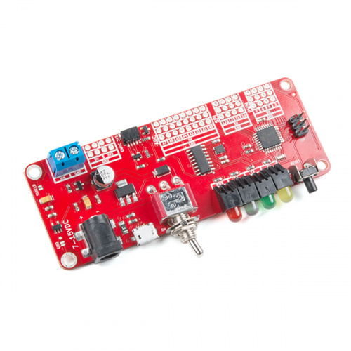
The SparkFun RedBoard Edge is a nifty little rework of the SparkFun RedBoard designed to be panel-mounted in your custom project enclosure for an easy way to make a clean, finished looking product. It has all the features of a normal RedBoard and is just as easy to use, even allowing you to prototype on a RedBoard and easily move your project over to a RedBoard Edge without complication. If you want an excellent learning platform for physical computing, the SparkFun RedBoard Edge is still a cutting-edge choice!
RedBoard Edge Hookup Guide
June 1, 2018
The RedBoard Edge is a RedBoard that's been rebuilt around the idea that projects are eventually put into an enclosure to help clean up their look.
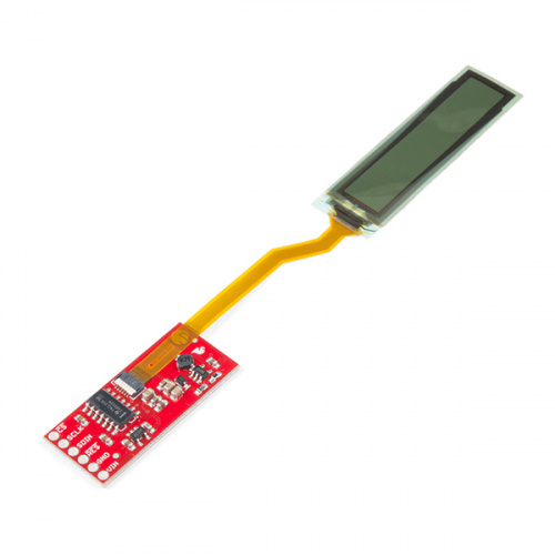
It's typically better to have a flexible mind and outlook on life, so the same should go for OLED displays! The SparkFun Flexible Grayscale OLED Breakout is exactly what the name says: a small, grayscale OLED that can be bent up to a 40mm radius without any worry of damage. Attached to a controller board, the actual display is less than 0.5mm thick and can display some impressive graphics (including BMP images, a variety of text options, or even a game of Pong) with great contrast.
Flexible Grayscale OLED Hookup Guide
May 31, 2018
Figure out how to get images displaying on your new flexible OLED screen.
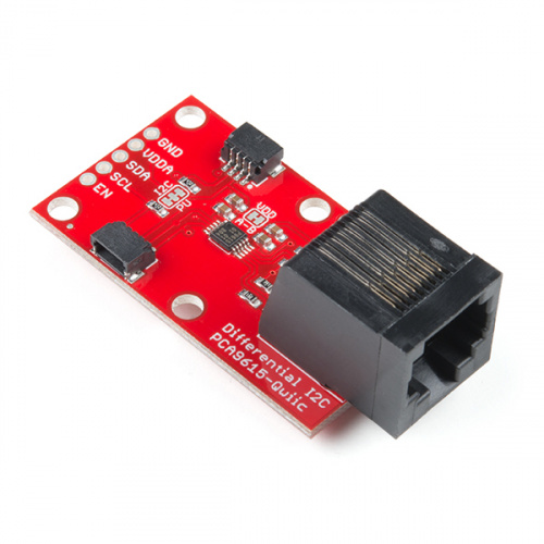
The SparkFun Differential I2C Breakout is the fastest and easiest way to extend the range of your I2C communication bus. The breakout uses NXP’s PCA9615 IC, which converts the two default I2C signals into four differential signals, two for SCL and two for SDA. The differential signals are sent over an Ethernet cable, which attaches to the breakout through the on-board RJ-45 connectors. The differential signaling allows the I2C signals to reach distances of up to 100 feet while still maintaining their signal integrity! To make it even easier to get your readings, all communication is enacted exclusively via I2C, utilizing our handy Qwiic system so no soldering is required to connect it to the rest of your system. However, we still have broken out 0.1"-spaced pins in case you prefer to use a breadboard.
Qwiic Differential I2C Bus Extender (PCA9615) Hookup Guide
May 31, 2018
Learn how to extend the range of your I2C communication bus with the Qwiic differential I2C bus extender (PCA9615 ) breakout board.
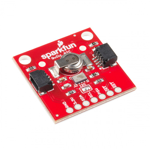
This SparkFun Real Time Clock (RTC) Module is a Qwiic-enabled breakout board for the RV-1805 chipset. The RTC is ultra-low power (running at only about 22nA in its lowest power setting) so it can use a supercapacitor for backup power instead of a normal battery. This means you get plenty of charge and discharge cycles without any degradation to the “battery."
Qwiic Real Time Clock Module (RV-1805) Hookup Guide
May 31, 2018
Find out what time it is, even after the power's been out on your project for a while with the Qwiic Real Time Clock (RTC) module.
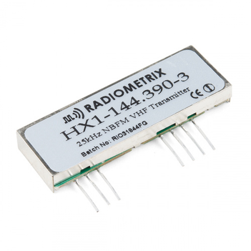
The HX1 is a low-power amateur radio transmitter set to a fixed frequency of 144.390 MHz. In North America, this frequency is used for the Automatic Packet Reporting System, or APRS.
APRS is a standard used by amateur-radio operators to broadcast live sensor data on a shared frequency. This data can be received by anyone with the proper equipment, and is aggregated on the internet through gateways run by members of the APRS community. APRS is commonly used to share real-time data including vehicle location (GPS), weather stations, high-altitude balloon tracking, remote sensor platforms, disaster relief coordination and more. It’s effectively an open-source, open-data, community-run, free-to-use IoT system with potentially worldwide coverage.
Alrighty, that's it for this week! There are plenty of options when it comes to new products this week. As always, we can't wait to see what you make with these products! Shoot us a tweet @sparkfun, or let us know on Instagram or Facebook. We’d love to see what projects you’ve made!
We'll be back next week with even more fantastic new products!



Nice to see Redboard Edge was designed using KiCad; hopefully this is a new trend at Sparkfun. Thanks N.Poole!
SparkX used KiCad for a while, and this design is from that period. We really liked it, but the rest of SparkFun still has a lot of production/ordering/inspection/QA processes that are currently built around EAGLE, so we found that the hand-off from SparkX to SparkFun took longer than we would have liked and incurred a lot of errors (from converting library components and transferring layouts) so we're using EAGLE 9 currently.
I really like some of the new features in EAGLE 9 but restricting the use of negative coordinates for cheap licenses is frustrating in a lot of cases. KiCad is great, too. If we could get the whole company on it, we'd probably do it, but right now that would be a lot of retraining and adaptation. That's time better spent making boards.
Meanwhile, if you're a KiCad addict and you haven't been keeping up with Shawn's Intro to KiCad video series with DigiKey, you should check it out!
I doubt it's a trend, but more of a new norm. When EagleCAD was purchased, the limited a lot of the features of the free version.
Reminder that you do need to have an Amateur Radio license to use the APRS transmitter. The ARRL (the national Amateur Radio club in the U.S.) has lots of resources to help you earn your license, including things like study manuals, lists of opportunities to take the exam, and links to local ARRL-affilliated radio clubs (some have license classes from time to time).
Most SparkFun customers should not have much trouble learning the "technical" stuff, but some of the "rules & regulations" stuff can be a bit daunting. From my experience, remember one simple principal for the "rules & regulations" questions: in an emergency, you are allowed to do what is necessary.
Hopefully all the GPIO pins are on a 0.1" grid. Never did understand why the original Arduino layout has 1 header row that's .05" off from the others, making it difficult to use with breadboard or to plug into a perfboard style motherboard.
I'm happy to report that the GPIO are all on 100mil centers! Arduino made a lot of design choices that I'll never wrap my head around.
Also, the standoff holes are spaced at 3.75" between centers the long way and 1.25" the short way in a good old fashioned rectangle.
The reason for that offset is to (help) prevent non-techy types from plugging "shields" in backwards. The Arduino was originally aimed at folks, especially artists, who had zero knowledge about electronics, but wanted to use "programability" in their creations. The "user community" for Arduinos has evolved dramatically from the original "target audience".
Seems they could have used an offset that was still on a .1" grid, instead of .05".
From what I've read it was actually due to a mistake/gerber file error in their first large batch of boards.
See post 4 on this Arduino Forum thread
Also reference from the Electronics StackExchange