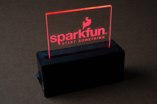
I've seen some pretty nifty edge-lit DIY projects. From the Death Star, to the USS Enterprise, to fun sayings or name tags, there are lots of examples.
A few months ago I got the idea to make some for some friends. Laser cutting various pieces of acrylic would be the easy part. The hard part was a base that non-techies could use and control with ease. I wanted several features, but didn't want to have to solder together five different boards for each one, so I ended up designing my own board, doing the assembly, 3D-printing enclosures and more.
Edge lighting is a fairly basic idea. When you shine an LED through a clear substance like a piece of glass or acrylic, it just goes straight through, but if you give it something to reflect off, such as a rough surface, it will refract the light, making that area visible. When you intentionally rough up or engrave a specific pattern it will light up, making a nice sign.
Quiz time: what is the most common edge-lit display you see on a daily basis? I haven't checked any official sources for this, but seeing as this is something I see daily and you probably do too, this is the answer I'm looking for. Winner gets to have a smug look all day for correctly answering a random online question.
A few of the features I wanted were:
- Powered over USB - I could have gotten a different power supply, but USB is so universal and cheap now that I wouldn't have to worry about spending more money on power supplies they would lose or have to remember which to use. Because the enclosure would be decent sized, I chose a full-size USB B port for its durability as a power jack (I did end up putting two footprints there if I change my mind).
- Capable of being programmed over USB - While I don't expect friends or family to program them, if I make a new piece of acrylic that I want a new fancy light display for, I want to just have them bring the device, plug in a USB cable, hit upload and be done.
- Be capable of running FastLED - This library does all the work for lots of different LED strips. I could use whatever strip I had lying around, just change one or two lines in the code and be done. The code actually has lines for the most popular options that are commented out. All I have to do is make sure the right one is uncommented and hit upload.
- Have a power button and a mode button - This allows them to change modes, which will most likely just be different colors and possibly a pattern such as rainbow or Cylon.
- Entirely enclosed - Some people (like engineers) like to see their electronics; most don't.
- Battery powered - I wanted the option to add a battery to this. That would allow the user to show off their new toy for a while before plugging it back in.
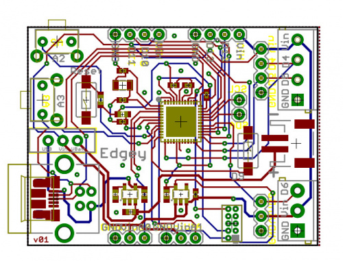
I chose the SamD21 chip as a nice powerhouse that can be programmed over USB and can handle the FastLED library. While it has more pins than I needed, I chose to break out a bunch of them anyway.
The board has two ports on the end that can take screw terminals (or just solder wires in). One port has power, ground and an I/O pin; the other port has power, ground and two I/O pins. This allows me to use one for WS2812s or other LED strips that only have one data line, and the other for APA102s or other LED strips that have a data line and a clock line.
I also broke out a couple of other ports with different I/O pins just in case, as well as a place for three different buttons. I spent some time digging into the graphical datasheet to determine which pins to use. There are a combination of SPI/I2C/digital and analog pins broken out. I also added a voltage regulator and battery charger with a JST connector.
Then I had to figure out power. Most LEDs are rated for 5V power (and data), but the SamD21 runs at 3.3V. After asking around, it sounds like while out of spec the APA102s will communicate fine at 3.3V, but they need closer to 5V to power them. I ended up running Vin to my ports, which is either directly from the battery or the USB port. Vin also goes to the voltage regulator to give the SamD21 3.3V, which it will use to talk to the APA102s (or WS2812).
Then there were the non-electronics parts. I dug around in a bin of buttons and switches, found some that would work and set about designing an enclosure.
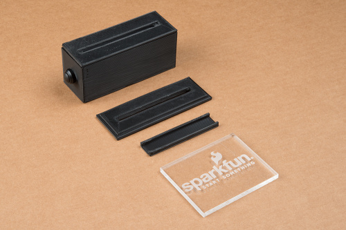
The current one fits the board snugly. Almost too snugly. If I had to redo the whole design I'd make the board as narrow as possible. One-and-a-half inches doesn't sound like much, but once you add a quarter-inch on each side and add some height, the enclosure size is pretty decent. That's OK, it still has to hold up the acrylic, and hold a power switch, USB jack and button for the mode.
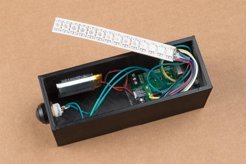
The next step is 3D-printing some enclosures, and laser printing some test acrylic. After some testing, I decided to add a small slot to the lid to slide the LED strip in (Scotch tape works very poorly to hold the LED strip to the lid). I ended up printing a separate piece and using 'ABS glue' (acetone and ABS) to connect it to the lid. While it is a bit hard to explain, you can see the small trough in the image below; it gets attached to the bottom of the lid, allowing the LED strip to slide in between it and the lid.
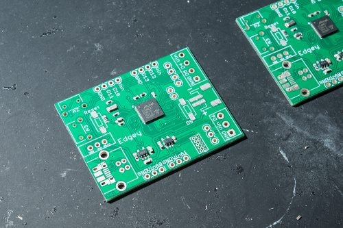
The next step was ordering parts. I got some PCBs on one of our QC test panels, since they had some extra room, and ordered a stencil. Time to build these up. As someone who never worked in PCB assembly I was a bit nervous, but things worked out pretty well (keep in mind trying to find 0402 components can be tricky). I got a couple of boards stenciled, hand-populated and reflowed with a hot air rework station (I was afraid of all my components blowing off if I walked them downstairs to the oven). After a quick test it was go time.
Once it was time to program I realized that my SamD21 wasn't getting any power. I had designed the board to connect Vin to either the battery or the USB port, but without a switch, it wasn't connected to either. This meant I had to add in my panel mount On/Off/On power switch to program the board. Once that was done I grabbed an Atmel ICE and got the bootloader up and running and was able to test my code. The code is fairly basic - a button connected to an interrupt changes the mode. The code runs through a switch statement and does something different for each mode.
After some troubleshooting and learning new skills I had a working project. I can cut new pieces of acrylic and just drop them in, and I can build more using the same board and same basic code using whatever LED strips I can find. I can switch between quite a few modes with the push of a button, and it doesn't look to the user like a bunch of wires and PCBs. I might choose to update the board and code to use Circuit Python and make it even more user friendly (might be nice for a master brightness control) now that we have that functionality on our SamD21 boards. Let me know what you think.
Interested in learning more about LEDs?
See our LED page for everything you need to know to start using these components in your project.



M-Short- Looks like I'm about 2 years behind on this article, I found to be very cool and interesting. It reminds how simple the most intriguing, curious things in life can be. I was wondering if you would be available to answer a few questions for me on an Acrylic Floating Shelf project that I would like to complete with LED lighting? Regards JK
This is awesome! I'm doing something similar -- right now it's running on a pi-zero-w, but I'm looking into esp32 as an option (I'm serving the controls through a web interface -- both on the pi itself to run locally, and a crazy AWS ec2 website that ssh's back into my pi to run the python scripts that change the light parameters).
I just... it's so cool except it's obvious that I cut into one of those cheap plastic bases to make it work.
Nice job :)
As a heads up, I've recently designed a few boards that have onboard WS2812s, and I've noticed that success with driving them with 3.3v depends on the USB voltage. I noticed that the 2812s worked when the board was plugged into my monitor, but not into a powered USB hub. I measured the bus voltages and the monitor was 5.05v, while the hub was 5.2v (both within spec).
I included a buffer on the boards as a level shifter, and haven't had any issues since. I used a small surface mount one that was about a quarter (74LVC1G125GW,125) - cheap insurance.
Thanks for the feedback, I designed the board to use both, but figured I'd likely only use the APAs which have been working with all the power sources I've given it. That is also another advantage to running it off the battery. I can plug it it and keep the battery charged, while running off the battery/charger output which is a bit lower.
My guess is the backlight for most LCD displays. Some of the newer ones have LED zoned backlighting, but most of them have a panel with two light bars along the edge.
As for the edge lit display we see every day, I see an automotive instrument cluster pretty much daily. The needles on the gauges in even very recent cars are still edge lit.
Hmm, hadn't thought of that. Not the answer I was thinking of, but a good one.
Great project!
I'll offer a few comments based on experience: I quickly found with NeoPixels that I needed to include a provision to measure "ambient light" and adjust the overall brightness based on that. (My projects with them would fall into the "wearable" category, so could go from bright sunlight to darkened room in a couple of seconds.)
Next, if you do decide to "respin" the board, I humbly suggest including a Qwiic connector -- I'm impressed by the variety of things that are compatible with that.
I heartily agree on the choice to use a USB power supply (I'm going to switch to them myself for some of my "IoT" projects), but although I agree that a full sized connector is probably more reliable, I'm thinking that since so many cell phones use a Micro B, USB cables with a full-sized connector on one end for the wall-wart and a Micro on the other end for the phone are practically everywhere, so I'd tend to go with Micro B. (I've seen those cables for sale even in the grocery store...)
On the size for the passives (which Haathi mentions), I, personally, have trouble working with anything smaller than 0603, and prefer 0804 or even 1206, for hand assembly.
And, as I think about it, I think Haathi is right -- the EXIT signs are ubiquitous.
I like the ambient light idea, that's another good reason to have a Qwiic connector. Even without the Qwiic connector though I did break out lots of pins from I2C to analog, I definitely could add it. I figure this will sit in a room, maybe act as a night light or something, so probably not too drastic of a change. Maybe on the next version I'll replace the button with something like the Qwiic Twist that has an encoder as well as the button.
I seriously considered the microB connector, there is even a footprint on the board hidden under the full size B if I want to go that route, but I know I'd break it off, so for now I'm sticking with full size B.
Yeah, those pesky 0402s can be tricky. I don't think I realized I was using them until I went to order parts, I just grabbed packages from the SFE Eagle library, and when you are routing a board everything looks much bigger.
Again, from experience, if you add the microB, put pads on the "back" side of the board (they can be isolated) that match (or are bigger than) the ones on the component side, and put several small vias between the two sides. This will provide mechanical strength to avoid breaking the connectors off. (There are also microB sockets that use PTH for mechanical strength in the mounts, though they're a bit harder to find, mostly because most pick&place machines don't like them.)
The Qwiic Twist was exactly what I was thinking! ;-)
I've used light sensors like this one from Adafruit on my "wearables" -- though it needs to be hooked to an analog input.
I'm going to guess "Exit Signs"
Good guess! Those things are everywhere.
You chose 0402 "as someone who never worked in PCB assembly?" I'm impressed! Nicely done on the board.
Also, I'm thinking of all of the edge lit EXIT signs I see every day.
When I've visited the UK, I've noticed signs that were "WAY OUT"... ;-)
Thanks, honestly placing them wasn't too hard, it was finding them that was tricky. I got all the parts from our production floor, some came as cut-tape, but at least 1 of the 0402s came to me as 15 or so parts in a ziplock bag.
And congratulations on being the first to guess the unofficial answer. Yes, most Exit signs (in the US anyway) are edge lit. But as these will be seen in just about every non-residential building in the country this was my first guess. Enjoy the "smug look" you get to wear today.
I've heard people talk about trying not to sneeze when placing SMD parts, but my problem always related to the tweezers. I would place a part perfectly only to bump it while releasing my hold on it.
Oh, don't worry, I will! Also, I donated blood today so I got cookies. Can this day get better?
I've gotta chime in with a heart-felt "thanks" for donating blood! Unfortunately they don't want mine (I've been on the receiving end, plus am on some fairly heavy doses of "blood thinners" because of a mechanical heart valve).