LiPower - Boost Converter
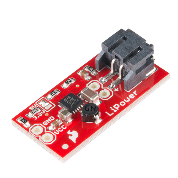
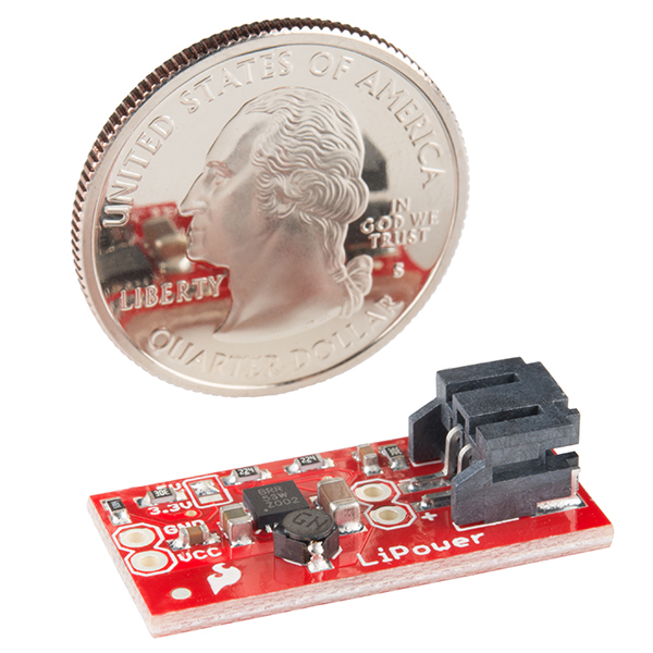
The LiPower board is based on the incredibly versatile TPS61200 boost converter. The board is configured to be used with a LiPo battery, has solder jumper selectable 5V and 3.3V output, and an under voltage protection of 2.6V. However, the board can also be used as a general purpose buck and boost regulator with an input voltage as low as 0.3V (default UVLO is 2.6V). With such a low input voltage and quiescent current , the board also works well in energy harvesting applications that use low input voltages.
Note: This board does not have reverse polarity protection, so please use the correct LiPo batteries (see related items below) or be sure to recognize the polarity if using your own input source.
Note: This product is a collaboration with Oleg of Circuits@Home. A portion of each sales goes back to them for product support and continued development.
- Input voltage 0.3-5.5V
- Output voltage 3.3 or 5V
- 5V @ 600mA max
- 3.3V @ 200mA max
- Undervoltage lock out at 2.6V
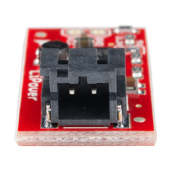
- LiPo JST connector or 2-pin header power input\
- Inductor: 4.7uH, 1.2A Sumida CDRH2D18
- Over temperature protection
- Schematic
- Eagle Files
- Datasheet (TPS61200)
- UVLO Modification
- GitHub
LiPower - Boost Converter Product Help and Resources
Single Cell LiPo Battery Care
March 16, 2023
This tutorial will go over how to safely charge, connect, disconnect, reinforcing the cables, and handle single cell LiPo batteries.
Application Circuit and Examples
The LiPower - Boost Converter's application circuit is embedded in the Power Cell. The Power Cell's circuit design [ https://www.sparkfun.com/tutorials/379 ] might be of some use. The option to charge a LiPo battery is not available on the LiPower since the charge circuit is not included with the breakout.
How to Modify the Under Voltage Lockout (UVLO)
You can find a nice tutorial here that shows how to modify what voltage the LiPower shuts down to protect an attached LiPo battery from over discharge.
Core Skill: Soldering
This skill defines how difficult the soldering is on a particular product. It might be a couple simple solder joints, or require special reflow tools.
Skill Level: Rookie - The number of pins increases, and you will have to determine polarity of components and some of the components might be a bit trickier or close together. You might need solder wick or flux.
See all skill levels
Core Skill: Electrical Prototyping
If it requires power, you need to know how much, what all the pins do, and how to hook it up. You may need to reference datasheets, schematics, and know the ins and outs of electronics.
Skill Level: Rookie - You may be required to know a bit more about the component, such as orientation, or how to hook it up, in addition to power requirements. You will need to understand polarized components.
See all skill levels
Comments
Looking for answers to technical questions?
We welcome your comments and suggestions below. However, if you are looking for solutions to technical questions please see our Technical Assistance page.
Customer Reviews
4 out of 5
Based on 5 ratings:
1 of 1 found this helpful:
Quite resonnable but not ideal
This part does what it claims. I am using a few in a project and they provide the regulated voltage and the specified current. I have had one unit fail but this could easily have been my fault.
I do have two negatives. The first is that there is no mouting holes like most of SFE parts. Would four holes for #0 or #2 hardware have added that much space? The second is that the spacing between the input and output voltage pads do not appear to be on 1/10 centers. Makes using this on a breadboard or perfboard dificult.
1 of 3 found this helpful:
Needs documentation
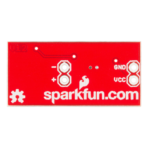
Can't figure which is input and which is output. The device is well built, but comes with no cables and only the identifying printing on the bottom to tell that you have input terminals and output terminals, but which is which, your guess is as good as mine.
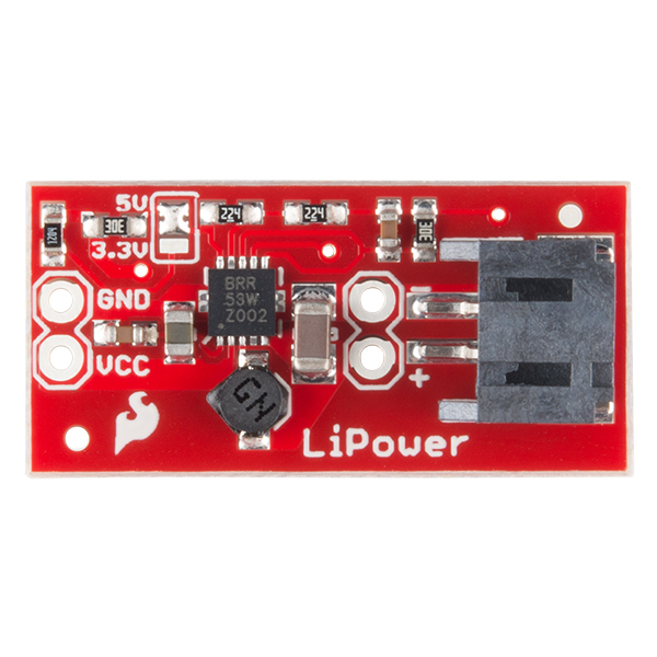
Hi, The input is on the side with the JST connector, there is also a second set of header holes in case you don't have a JST connector on your power source. The output is the side that is opposite the plastic JST connector. The schematic will help you determine this information if you find yourself unsure with other products. Happy hacking!
Works great
I've used 4 or 5 of these boost converters for little projects here and there. They work great. I've even swapped resistors around to make them simulate a fully charged LiPo battery at 4.2v.
Do pay attention to the amperage curves in the datasheet for the boost regulator. In my case, I was making 4.2v (I had swapped resistors) from a 1.5v source, but I had peak amperage requirements that were outside the curve for the regulator. The circuit would brown out. Increasing the input voltage (two AAA cells in series) put me in the sweet spot.
As Expected
It works pretty well, I am glad to purchase this product.
0 of 1 found this helpful:
My soldering skills are terrible
I attempted to convert the output to 3.3V, but my cold blunt iron just scraped the pad off the PCB. Done! 😕 I didn’t even get to power it up.

The link for the UVLO Modification has changed. This seems to be the new website: https://chome.nerpa.tech/dc-dc/tps61200-board-modifications-part-1-changing-undervoltage-lockout/
Would this device work with one of the Li-Ion batteries Sparkfun sells? Something like this.
Hi, what is the weight? I am building a light weight setup... so.. weight is important! Thanks!
I don't usually check the comments but I happened to notice yours today. The packing weight of this product is listed as 0.0040 lbs. =)
How could this be implemented into a permanent project in which disconnecting the battery for any purpose isn't an option?
Hi guys, I have a question, does this work if I want to convert a 0.3+V input to anything greater than 0.7V basically a logic HIGH for an arduino uno? And do I basically just solder my 0.3V pin on to the Vcc (and solder the GND of course) as input and the output would be from the pad marked 3.3V?
Thx!
Hello, I've been using quite a few of these and now that my prototype has been working i am wanting to integrate this into my own PCB. Unfortunately I am having issues with the output, it seems to give me 6.2V oppose to the 3.3 I wanted. I don't think This possible given the data sheet, but I hand soldered it. could this have caused damage?
I would upload a pic of my schematic but I'm not sure the comment system on spark fun allows for that. Any help would be appreciated.
Figured out I ordered the TPS61202 not the TPS61200. The former is a 5V fixed regulator.
Is there a Fritzing file for this part?
Im still learning electronics so please forgive my newbish question. Are the specs above the output max or input max? Im referring to the 5V @ 600mA.
Im looking to possibly use this with a 3.7v 400mAh LiPo battery to power an Arduino Mini and several LED's. Is this good or should I look at getting a step-up converter instead?
Hello, Hard to see from the pictures how to select 3.3 or 5V output. Can someone clarify?
picture
It's a solder jumper at the top left corner of the board.
I'm using this part to power a simple circuit which requires 5V. When connected to a 3.7V power source, the circuit (including the boost converter) drains 320mA.
Everything works well when powered by a single cell, 400mAh Li-Po battery (PRT-10718), but the battery does not last long enough for my application. When I connect this higher capacity battery (a brand-new Mudder 680mAh 20C Li-Po):
http://www.amazon.com/Mudder-Upgraded-Rechargeable-Battery-Quadcopter/dp/B00S65G8VQ/ref=cm_cr_pr_product_top?ie=UTF8
The output of the boost is 0V. The Mudder battery works well if connected to a different boost converter, such as this one:
http://www.amazon.com/DROK-Adjustable-Automatic-Buck-Boost-Converter/dp/B00GWCC6S4/ref=sr_1_1?ie=UTF8&qid=1422888984&sr=8-1&keywords=DROK+Adjustable+Automatic
what can be the cause of the problem? Any idea?
Is this 600mA output max or input max?
has there been a revision to the currently shipped unit? UVLO resistor and cap are now perpendicular to the edge and the 3.3/5v jumper has swapped position?
Does anyone know where I can get some of the inductors used in this? I have used some out of the Sparkfun Eagle library when designing a PCB, now they are being printed, and I cannot find where to buy them at all? Would Sparkfun be able to sell me 5 or so from their stock? :(
I believe this is it: http://www.digikey.com/product-detail/en/CDRH2D18%2FHPNP-4R7NC/308-2297-1-ND/4356367
I haven't tested it but it looks like all the specs match up.
While LiPo batteries have a voltage of roughly 2.5 to 4.2V, they drop off fairly quickly after they hit 3.5V, which means using this part in a 3.3V project will run the converter in the extremely inefficient (~75%) step-down region for most of the time. Consequently, I wouldn't recommend using this part for 3.3V projects that are LiPo-powered.
Most designs I've seen actually just use a buck converter to step-down the voltage -- when the battery voltage drops below 3.3V, the converter will track the input voltage. This may seem counter-intuitive, since you don't "squeeze out" all the juice in the battery -- however, the increased efficiency of the buck solution means you get longer battery life overall.
One article I read indicates at 300 mA output current, a buck converter got 9 more minutes of battery life than a buck-boost converter of similar configuration: http://www.eetimes.com/document.asp?doc_id=1273123&page_number=3
Obviously, if you're building something with ultracaps or other low-voltage stuff with UVLO disabled, this is a great part to use. And it definitely shines at 5V output -- I'd just stay away from using it in a 3.3V configuration with LiPo batteries.
Maybe I'm reading the TPS61200 datasheet wrong but the "Efficiency vs Input Voltage" graphs don't seem to show the substantial efficiency fall-off you describe. For a 500mA current it seems to show efficiency at always above 80% for the input voltage range 2.5V to 3.5V with 3.3V output and above 85% for the same range with 5V output.
MORE CURRENT!!
Come on SF, throw us a bone. Give us something we can put between a 3.7v 2Ah LiPo cell and our Raspberry PIs, beaglebones, etc. I’m willing to pay for it, it just doesn’t exist
Hi, trying to use this to boost a 0.35v source to 5v USB power (no lipo connected). I removed the UVLO but it won't react until I raise the input to 0.8v, then it outputs a fine 5.0 volts. Problem is I need to get down to at least 0.5v input, which the specs says will deliver full power. I've had the unit lying around in a bag for a while, might it be broken?
This board would physically fit my current [tiny] project better if I trimmed off the JST connector end, repaired the cut traces w/ jumpers. While studying what I'd be cutting/jumping, I noticed the board pictured above looks different from the eagle files below, notably in the orientation of the caps in the upper left corner, near the output, and the position of the via near the JST connector. In the photo, the via is right next to the caps, whereas in the .brd file, it's much farther to the right, above the JST connector, would be cut off. Which is accurate, reflecting what you currently ship, the .brd file, or the photo above? Anyone else have trouble opening the alternate .brd files on github? ("Error: line 7, column 6: This is not an EAGLE file.")
Why is this circuit, which uses the same TI TPS61200 as the arduino mini FET shield's power supply, rated to provide so little current at 3.3V, while the FET shield is rated at 600ma, and per the product description has been tested to produce 2A at 3.3V?? The only component with any current passing through it seems to be the inductor, and it's rated for 1.2A per this schematic. Per Fig9, with a 1A 3.3V load and power save disabled, efficiency remains between 80% and 90% between 3V and 4.2V, the normal operating range of a LiPo cell. Per the same Fig9, for a 500mA load, under the same circumstances, the efficiency curve looks worse, but still ranges between 68% (for a fully charged bat at 4.2V) to 90% at 3V. Is there some part that's hobbling the output in this circuit?
I'm designing a stripped down modification of this with only 3.3v operation without UVLO (minimal parts).
For UVLO bypass, I've removed R3, R4 C2 and tied UVLO directly to VIN (correct?). For 3.3v operation only, I've removed SJ1, R7.
And as a result of this, GND pin is now connected to R6 and then to FB pin (and then to R5 and VOUT). Can someone tell me if this is right?
edit: schematic reads fine now
also the circuit is drawing over 8mA DC when supplied with 3V for 5V output at no load. With 5V input, the current drops to 100uA, both above the spec'd 55uA. Anyone else experience this?
final edit: the high current is because power save (PS) is disabled on this board. I bought the TI eval board from a different vender and pulling PS down drops the current. Disappointed.
I measure over 8mA current draw when supplied with normal LiPo. I think the product info should be changed.
Will this device output power even when a battery is not connected?
I just got one of these and the smallest Li-Po battery SparkFun has. Anyway I had it working when I first got it, put it in a box for a couple weeks, but left the battery connected(bad idea?), now when I give it power -- 5V, I get 0.06V on the battery side. Is it the battery or booster thats broken? Did I break the battery by leaving it connected to this device?
What is the heat protection device used? Is it just a heat sink?? Should I have active temprature control if I keep it on for long hours at maximum rating?
The IC shouldn't get hot at its max current draw. Obviously, going over could result in heat and/or lack of efficiency .
What is the 'GW' marked cylenderical device? I'm really interested in its working.
That would be the inductor, part# CDRH2D18/HPNP-4R7NC.
What size is it?
What's the point of the three vias underneath the chip?
It's a combination of thermal and signal integrity. See page 17 of the datasheet. Also, there is probably a TI app note out there somewhere that gives example layouts. Most switchers like this recommend vias under the IC and connected the center thermal pad (under the IC).
Hey, I'm a tad unsure if this is what I am looking for. Can I use this to charge a LiPo battery from say a small motor and then use the same board to discharge to a cellphone or some sort of device? Could I do both? Charge my cellphone and when the battery on the cellphone is fully charged it overflows into the LiPo for later consumption?
This board isn't designed to be used as a battery charger. It is a buck/boost regulator board. I think what you are looking for is the Powercell.
Hello everyone. I have a basic question.
From wikipedia: UVLO is an electronic circuit used to turn off the power of an electronic device in the event of the voltage dropping below the operational value.....
Why does the device need to worry if the voltage goes below the operational value? if it does, why does the device need to turn off? I don't see how a lower than needed voltage could harm the device. It surely does not allow it to work properly but it would not damage it, correct?
It can be very bad for certain battery chemistries if you drain them too low. LiPo batteries can form shorts within the cells if they go too low and this can be very hazardous. An UVLO is used so that once the battery reaches a certain voltage, the external load to the battery is cut off.
Guys,
To get the circuit working at 3.3v with the UVLO removed (as per the linked artical) requires not only connecting the UVLO pin to VIN as described in the article, but also the removal of R4, as otherwise R4 upsets VOut.
Thanks Kev
I love this little board for all my LED projects as I work with 5V strips and Arduinos and everything needs to be as tiny as possible. I saw off one end of the board to make it even smaller. I did have to repair once as I sawed off too much, breaking a connection that runs to the ground terminal on the input. Why it needs to run all the way around is a mystery to me, as it can be made much shorter.
Also, I would like to see a reverse polarity protection. I already fried one of these boards instantly as I didn't get the + and - right. Stupid of course, but still, would be nice to have protection from that.
So I shorted the outputs for a few seconds i believe. It got really hot and all i can get are 3.3V if i remember correctly. My battery was at 4.2V. What I would like to know is the inductor salvageable? Its showing 0 ohms with a multimeter. I guess the failure mode it's called? Thanks,
Why did you add C2?
It has to do with the hysteresis of the UVLO, which will add to UVLO level. The cap creates a temporary short when powered on, which allows the UVLO to stay off for a short period of time while the unit stabilizes after powerup.
Can we get a revision of this board that is a bit easier to mod, like for through-hole resistors for the under-volt lockout. Soldering these, or extention wires onto to those tiny surface mount resistors isn't exactly mechanically sound engineering.
I like the small footprint as it is. But I guess expanding it's size for that wouldn't take that much.
Is there something like this but that can supply more current? I'm trying to power a BeagleBoard from one of the lipo batteries and it can draw up to 1.5 amps.
Could this be used for charging a 5V 3F Supercap from a set of low voltage (1.89V Max) solar panels? I'm trying an energy harvesting project and am hoping to fully charge the capacitor. Would any circuitry be needed between to converter and the capacitor to limit the input current/protect the boost circuit from feeding what will basically be a short circuit when the cap is fully discharged?
Thanks
I found a note at http://tinyurl.com/SolarSuperCap, that discusses using the TPS61200 for charging super-caps from solar panels. Looking forward to trying it out.
Its been asked several times before, noone commented yet. Can I combine 10401 (LiPo Charger Basic) and 10255 (LiPower - Boost Converter) directly? Like one box with two USB connectors and a Lipo inside, where I can connect either a computer to charge the Lipo, or a mobile to charge this. Or even connect the box to an unreliable 5v source (bicycle generator comes to mind) and have the Lipo as kind of a USV?
I basically would connect the Lipo to both the charger and the step-up-converter, all three of them in parallel.
Any thoughts greatly welcome!
It should work fine. In fact, that is exactly one this one is: https://www.sparkfun.com/products/11231
great product guys. I had been looking for such a device, but having to find all the precise external components really put me off. So now I can just use this, and be confident that it works right.
Correct. This is an analog design, so using this IC is not straightforward.
I have an arduino mega pro mini 3.3v, would this help improve its battery life?
I have an arduino mega pro 3.3v, would this help it improve its battery life?
I've ruined a few of these with my poor soldering skills. What i wouldn't give for an identical board with through holes to change voltage and ULVO. Based on the comments, it's possible that more people are modifying these than using them out of the box.
Hi all! Does anyone know how this booster compares to MintyBoost circuit when talking about efficiency etc? Disconsidering the fact that MintyBoost already brings the USB connector and pull-up resistors on data pins, so that usb devices can see it as a charger. Thanks
i built a circuit using the same chips as Mintyboost but for 3.3v (you just have to change the signal on one pin). It worked great, but i couldn't drive analog sensors with it because the output oscillated a bit to much. I easily drive analog sensors with this part.
Hello, sorry for the dummy question, but I'm not a hardware guy. Is it possible to connect the Lipower to a PRT-10217 basic USB charger for lipo battery ? The idea is to refill the lipo and run the application when connected to USB, and without any change in the connection, use the lipo hen disconnected from USB ? Does it make sense, or maybe is there an "all-in-one" board designed to work that way ?
Cheers,
Pierre
For me it is not totally clear how one uses this component. I attach the LiPo to the JST connector, a solar cell to the input and that's all? The chip will handle LiPo charging just fine? Or do I need some other components?
I would like to build a system that uses solar power to charge a LiPo and uses the LiPo to drive some low power electronics. An mCU and some leds for example.
Can someone point to such a howto? As LiPos are considered dangerous I would like to clearly understand all bits. Not just wire the thing together and hope it will not blow up.
This guy will let you do things like run your microcontroller off some capacitors(http://www.sparkfun.com/products/746) by boosting up the voltage to something more useful. If you want more info on solar charging look at http://www.adafruit.com/blog/2010/07/09/how-to-make-a-solar-mintyboost-a-solar-power-charger-for-your-gadgets/
How do I select between the 3.3 and 5v outputs? I see the solder points, but how? I can't find any instructions.
Thanks.
Have a peek at the first photo in the product page. You see how there's 3 solder points, and the the middle solder point, and the solder point close to the 5V label are bridged with a glob of solder? That's what selects the 5V. If you want 3.3V instead, you'd bridge the middle solder point and the solder point closest to the 3.3V label.
If it is already bridged for 5V when you get this, make sure you desolder that bridge. I recommend litz (the braided thin copper strands stuff) rather than a suction pump, and use a multimeter (or just a battery + LED) to make sure the solder bridge has been removed.
Thanks! I see it now.
The QFN library part does not pass DRC, eagle does not like weird pads... agrrrr!
What are your drc settings?
The problem is the thermal pad, SF made it by joining 5 different pad shapes. I guess they had to resort to this workaround because eagle does not allow custom pad shapes, This causes the DRC to fail because pads overlap.
Have to figured out an easy fix to this? I've ran into the same issue.
You could make an eagle part that jumpers the two together in the schematic. In the board file, the jumper could just be a short trace of copper. Then you won't have DRC errors. Or you can just approve the errors.
According to the data sheet, PGND and GND must be connected on the PCB. I don't see this on the schematic. Am I missing something?
They are connected together, through pin 9. The schematic doesn't show this.
Anybody knows if it has active current limit? i have used it with a 0,8A (Xperia X10 mini pro) load and i think i have damaged it...
I know there is some explanations in the web about how to limit a DIY iphone charger (http://www.crunchgear.com/2008/07/27/diy-iphone-charger/)(a voltage divider in D+ and D- USB data lines).Has anybody try with other devices with data detection at charge time? (Samsung YP R1, battery hungry....or Xperia X10 mini pro, to limit the charging current?)
Thanks a lot, guys!!
It can only supply up to 600mA max at 5v.
Thanks, I know. I have already read the datasheet.
What i want is limit the charge current like de mintyboost does. Take a look at the link i posted. With the voltage divider, you can configure the charge current. The voltage at the D- and D+, set the charge current, and "says" to the device to take 500mA instead a maximum (default) setting of 1.3A, for example in the ipod,or 0,8A in my Xperia.
any ICs capable of putting out more? I'd like to have 750-800ma available if posible to drive 3 LED displays from a 3.7 2000mah LiPo battery.
Edit: Looks like Maxim's MAX1797 is capable
Would there be any issue in using this in conjunction with http://www.sparkfun.com/products/10161? I would be taking the output 3.7v on the charger and into this.
Is connecting several lipo batteries in parallel to this safe? Or should there be some sort of distribution/protection circuit?
Question: Would this board be a good way to allow lower voltages to be used with:
http://www.sparkfun.com/products/9946?
Thank you,
mike
Weight as shown is 1.6 grams.
I agree the 2.6V ULVO limit is good for li-ion cells/packs, but i would love to have one of these with a lower limit. Datasheet says it can go right down to 0.25 volts, and that would be awesome for use with a single NIMH cell, or as a replacement board for the 100 mah 2xAA 5V dc step-up board you guys currently supply (of which i own two). Alternatively, if you could include instructions on how to modify your board to bypass the 2.6V limit you have placed? Either way, I will very likely buy one of these soon :)
@SlyVixsky there's an easy way to do the mod, ie: no soldering.
1) Locate the via next to the UVLO pin.
2) locate the pair of + and - pads next to the JST connector (ie: the plated through hole pads.)
3) connect a jumper wire from the via to the +pad.
The via is a little bit tight but the mod works... UVLO disabled. :]
Just did this mod and it worked great, thanks!
I think you'd have to remove R3 and R4 (and C2 if you want), then tie UVLO to VAUX. That's from the pads between R3 and R4 to the positive side of the remaining small capacitor.
Are the specs correct? It seems odd that it puts out 600ma at 5v (which requires a bigger boost), but only manages 200ma at 3.3v. Perhaps these values a reversed?
Hmm.. well, the datasheet says 600ma at 5v and 300ma at 3.3v, so I guess the specs above are correct.
The TPS61200 is an unusual part in that it can function as a boost converter, but it can also output a lower voltage than the input. The boost mode is more efficient, which is why 3.7V in / 5V out has a higher current limit than 3.7V in / 3.3V out.
Nice!