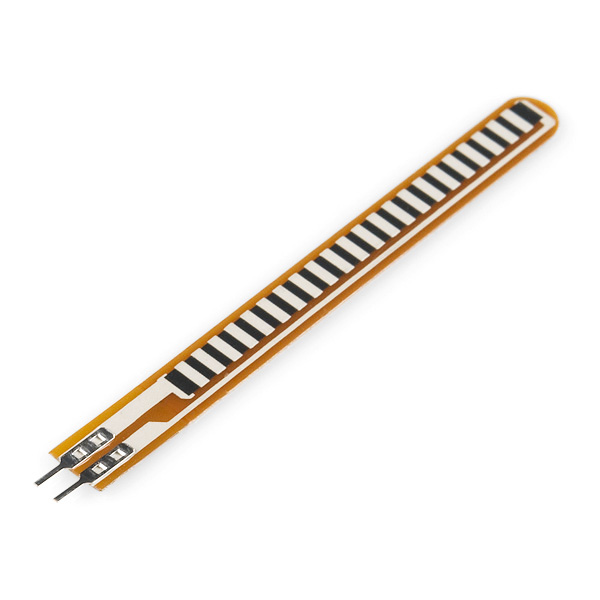
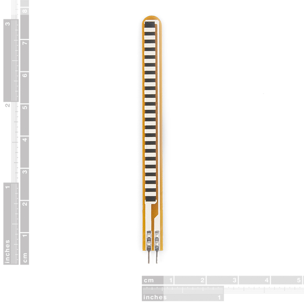
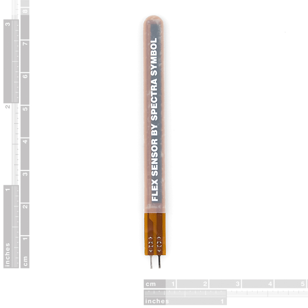
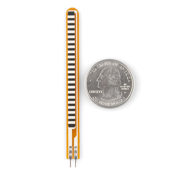
A simple flex sensor 2.2" in length. As the sensor is flexed, the resistance across the sensor increases. Patented technology by Spectra Symbol - they claim these sensors were used in the original Nintendo Power Glove. I love the Nintendo Power Glove. It's so bad!
The resistance of the flex sensor changes when the metal pads are on the outside of the bend (text on inside of bend).
Connector is 0.1" spaced and bread board friendly. Check datasheet for full specifications.
Note: Please refrain from flexing or straining this sensor at the base. The usable range of the sensor can be flexed without a problem, but care should be taken to minimize flexing outside of the usable range. For best results, securely mount the base and bottom portion and only allow the actual flex sensor to flex.
Flex Sensor 2.2" Product Help and Resources
Flex Sensor Hookup Guide
May 5, 2016
An overview of the flex sensor - a bendable variable resistor. Plus, example circuits and Arduino code to get you started!
Qwiic Flex Glove Controller Hookup Guide
July 19, 2018
Is your finger bent? Is your finger straight? The Qwiic Flex Glove controller board will answer this age old question for you with the flex sensor!
Core Skill: Electrical Prototyping
If it requires power, you need to know how much, what all the pins do, and how to hook it up. You may need to reference datasheets, schematics, and know the ins and outs of electronics.
Skill Level: Noob - You don't need to reference a datasheet, but you will need to know basic power requirements.
See all skill levels
Comments
Looking for answers to technical questions?
We welcome your comments and suggestions below. However, if you are looking for solutions to technical questions please see our Technical Assistance page.
Customer Reviews
4.3 out of 5
Based on 15 ratings:
1 of 1 found this helpful:
Working perfectly and great range of values
I'm using this in a MIDI controller glove and it has been working great. I'm getting resistance values ranging from 30kohm to 130kohm! As others have mentioned, it's a good idea to secure the base onto something inflexible as that part isn't really intended to bend.
1 of 1 found this helpful:
finally in my hands
I got the sensor and perform the corresponding test. all in prefect condition. thank you.
1 of 1 found this helpful:
The leads are very thin!!
The leads are very thin and bend very easily when students try to put them into the breadboards. Functionally, the sensor works great
1 of 1 found this helpful:
The Base is poorly Designed
Right above the solder tabs, the very flexible base bends everytime the flex sensor is bent I.E. leading to high probability of it breaking. Apart from that its good.
1 of 2 found this helpful:
Really Easy to Use
I thought I might need some special OpAmp circuit to get a decent range of readings from this. It turned out that my DMM set on reading resistance was more than adequate.
1 of 2 found this helpful:
Acceptable
The flex sensor worked well, but in my opinion both the sensor and the shipping was too expensive. About 11 dolars for a small sensor is too much.
Very happy
I purchased these sensors for a robotic hand project and the work perfectly, but they are a little bit expensive.
Never received it.
I never received it. Would like a refund.
Sorry to hear you never got your part. Please fill out a return form and we will make things right: https://www.sparkfun.com/returns
Flex sensor
surprisingly sensitive. I’ve been trying to sense movements in a solar collector with strain gauges. Whereas a strain gauge is far more stable and repeatable, this sensor changes value when flexed and needs little or no amplification for a detectable signal. I see why they are used in gaming gloves.
Great flex sensor - can detect both directions!
Flex sensor is very responsive one way, and also has some sensitivity (going down to about 22kohms) when flexing backwards. Quite handy!
To fragile and electrodes to small
I Think it is to fragile and the electrodes is to small, and it is to easy to damage it Beyond repair.
Hello!
Sorry to hear about the issues with the flex sensor. Have you contacted our technical support department @ techsupport@sparkfun.com about this issue? They may be able to help outline use cases that show what uses we have found these effective in and help find a way to use them without easily damaging them.
I love it!
i really like this item for my project


Will applying a 3.3V to the flex sensor reduce the sensitivity of the readings?
Hi there, it sounds like you are looking for technical assistance. Please use the link in the banner above, to get started with posting a topic in our forums. Our technical support team will do their best to assist you.
I would recommend starting with the flex sensor hookup guide and the resistors guide.
Anyone know if this can be used directly hooked up to a Spectacle Button Board? Like could it be used as a button? Or does it need more than that? Thanks!
Unfortunately it won't work. This has a variable resistance and can have one of many values. A button only has 2 states (the 2 sides are connected or they aren't).
Judging from the limitations noted by the commentators below, the sensor sounds like it's intended for use as some sort of toy, not for professional measurement applications. I haven't looked yet, but maybe there are higher quality models out there. Probably more expensive, though.
Would sensitivity and dynamic range improve if the sensor were employed as one leg of a bridge circuit, with variable resistor on the opposite leg? The latter can be used to set the zero-point resistance. Can't we improve the sensitivity and range even more by connecting a differential op-amp with high common-mode rejection (i.e., so-called 'instrumentation amp' ) between the 2 legs of the circuit ? This is a common way of measuring other commonly used resistive sensors. Of course, you eventually will run into the sensor's absolute lower limits of sensitivity, accuracy and noise.
Hmmm, the datasheet says 25K to 125K ohms, the Quickstart says 30K to 50K, the Oomlaut Project says 10K to 35K and the one I got is 18.5K to 21.5K and not very consistent. It doesn't seem to be a very reliable component.
The newbiehack video says you will get from 25kOhms to "as much as" 125kOhms. Yet another example of sly ad copy.
Lucas Barton would approve.
What's the story on the stiff backing (seen in the 3rd product picture)? Is it mean to be peeled off so this can adhere to a substrate? That's what it looks like, but I had some older models lying around which don't have this backing and they are much more flexible. Just wondering if anybody else had noticed this.
I recently bought 10 of these sensors for a project, and after testing all of them with my meter, I only got a reading between about 30kΩ and 35kΩ. This range is going to be very hard to work with for the project. Has anyone else been able to reach the alleged 50kΩ of resistance with these sensors? I have tried flexing in many different manners with all 10 of the sensors, but haven't come anywhere close to 50kΩ. It seems very unlikely that I would have gotten 10 defective sensors, so I must conclude that these sensors have some rudimentary design flaw.
Is it bi directional?
Not according to the Newbiehack video tutorial. It only changes resistance when flexed in one direction.
Hello, are sent to Argentina? the cost is in dollars? thanks, sorry for the ignorance, I'm new.
Check out our FAQs. This should answer most of your questions!
Nice instructable on how to build these at http://www.instructables.com/id/How-to-Make-Bi-Directional-Flex-Sensors/
Hi, can this sensor be flexed of 180 degrees without taking damages?
At 180 degrees, you are going to be bending the sensor at the base, which will have a negative affect on the functionality of the sensor and may damage it, so I wouldn't suggest it.
can this flex force be used in an insole gait monitoring system for a person with a weight of 65Kg
Good sensor but would be better if they all come in at the same resting value.
You have to be careful soldering wires to them , Just solder to the tabs that stick out, from the sensor, otherwise they have a tendency to go open circuit.
Cool product. I was just going to make a videogame controller glove, and I though flex sensors would work best. It's funny to see it's already been done in the exact way I had planned my own project!
These have exactly the same design flaw as the 4.5" sensors: Even though they are flex sensors the area between the pins and the sensor is incredibly susceptible to flex damage where the Kapton traces lift or wear. We went through a few of these before we finally reinforced the connection area enough to get over 1000 cycles, much less the >1 Mil that the data sheet claims. (Look at the photo of the back to see the area where the sensor reinforcing stops more than 1cm before the connector.)
Any component that undergoes routine physical contact should have some sort of strain relief E.G., Phono plugs, power cables that traverse casing walls, Piezo Vibration Sensor sku: SEN-09196, etc.
Yep, exactly. It is up to you to provide your own strain relief.
This product does include strain relief, however it does leave an area between the connector and the sensor vulnerable. Again, not something a hobbyist would expect in something labeled "flex sensor".
Reading the number of commends around the 'net plenty of other people have had the same issue and ruined their otherwise excellent sensors as a result. Seemed fair to provide a warning here.
It's -not- a warning to avoid the sensors (quite the opposite) but to take extra care when using them.
Most devices out on the market, excluding external connectors (phono plugs etc...), will not come with any type of strain relief as the assumption by the components manufacturer is that it (the component) is being sold in bulk to a OEM (original equipment manufacturer) who will engineer the casing and any strain relief necessary to keep the end user from destroying the device under normal use.
The spec diagrams show both a part length and an active length. The active length does have some reinforcing but it is not an actual strain relief. The strain relief design, as hinted at above, is usually use specific and will vary due to application, casing and physical electrical connection. You sometimes learn such things in design classes.
In this case the reinforcing should be clamped to some part of the case the PCB is mounted in.
Rule of thumb, take a long look at any device that will move or be manipulated by the end user. Look for the weak link in its design, then look for ways to brace/connect it to the casing or PCB other than its electrical connections.
"Normal use" is one of those fine print lawyer words.
Very much agree here
Fair enough. But at the same time, we've sold thousands of these and only a handful of issues. But, yes, they can be fragile if used in certain circumstances.