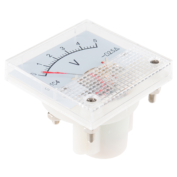
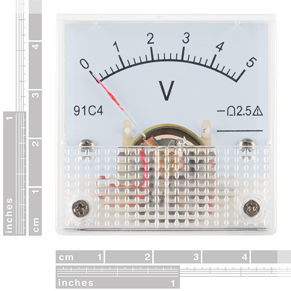
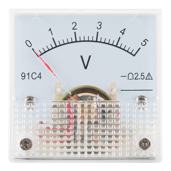
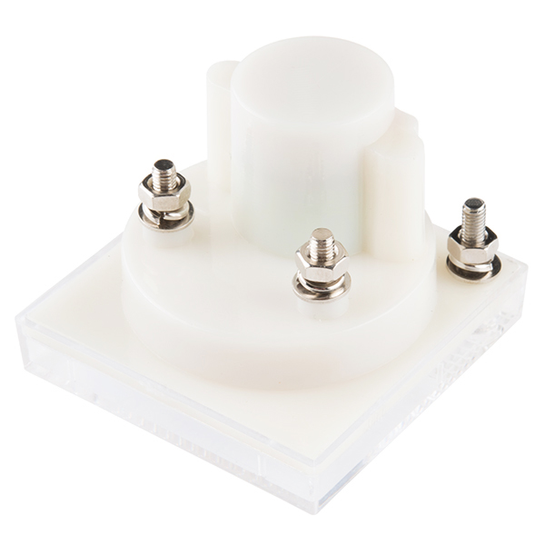
This analog panel meter measures DC voltage from 0-5 volts with 2.5% accuracy. It has a clear and easy to read scale and an adjustable dial. These come in handy for measuring the output of sensors with 5V ranges.
The face of the meter is 45x45mm overall. The mounting hole should be 38mm. The overall depth of the meter is 35mm.
Analog Panel Meter - 0 to 5 VDC Product Help and Resources
Core Skill: DIY
Whether it's for assembling a kit, hacking an enclosure, or creating your own parts; the DIY skill is all about knowing how to use tools and the techniques associated with them.
Skill Level: Noob - Basic assembly is required. You may need to provide your own basic tools like a screwdriver, hammer or scissors. Power tools or custom parts are not required. Instructions will be included and easy to follow. Sewing may be required, but only with included patterns.
See all skill levels
Core Skill: Electrical Prototyping
If it requires power, you need to know how much, what all the pins do, and how to hook it up. You may need to reference datasheets, schematics, and know the ins and outs of electronics.
Skill Level: Rookie - You may be required to know a bit more about the component, such as orientation, or how to hook it up, in addition to power requirements. You will need to understand polarized components.
See all skill levels
Comments
Looking for answers to technical questions?
We welcome your comments and suggestions below. However, if you are looking for solutions to technical questions please see our Technical Assistance page.
Customer Reviews
4.1 out of 5
Based on 9 ratings:
1 of 1 found this helpful:
Very well put together
I got this and I was expecting to a cheap plastic face, but the whole feels very sturdy, I'm not entirely sure however about the accuracy, this versus my multimeter gave me a +/- 0.25 volt reading, which in the grand scheme of things isn't that big of a deal. Overall, it's fantastic.
1 of 1 found this helpful:
A meter
I seems to be working correctly. Th price is great.
McMaster Carr wants $100 for panel meters.
1 of 1 found this helpful:
Different from the picture - No adjusting screw
I expected the voltmeter to look same as it's shown in the picture, but it wasn't There are no adjusting screw in the real product as in the picture. I'm little bit frustrated.
I'm sorry. We try to keep up with out images as parts change. I'll get these updated. If you would like a return please contact us at www.sparkfun.com/returns
1 of 1 found this helpful:
Goodie
I mistakenly thought there would be set screw, but turned out, wasn't, my fault, didn't read description.....But, otherwise well made, enough accurate meter, kinda cute, being so small. Okay, back to topic, since it's DC meter, polarity matters, and it's marked backside (negative is marked, but enough) Good if you need approximate reading, not that precise, just what I was looking though with.
2 of 2 found this helpful:
I may be able to get it to work
appeared to be broken, but may just be the zero adjust. (*accessible one you take off the clear plastic cover.) accuracy is a bit worse than expected- i am looking at closer to 5%-10% error. it does lend a kind of cool look though. I will revise if i see better result beyond "the breadboard"
1 of 1 found this helpful:
Great Meters
These meters met my expectations for the project that they were intended for. Small size and accurate for analog meters.
1 of 1 found this helpful:
Should be 4.5 stars...
Works exactly as advertised. 1/2 star deducted because:
The bag holding the nuts and washers broke open and they were floating around in the box. (But they were all there.)
The orange paint on the pointer had largely flaked off. (Easy to repaint)
1 of 1 found this helpful:
It works
I used this for a kids toy for my cousins son. It looks great as the center-piece of the board and it works fine as well.
works as advertised
wish there was a hole diagram somewhere, I had to measure it myself. also needed to drill a small hole to allow access to adjust 0


I just dropped one of these into the panel of a musical puzzle box that I built for some kids. The indicator moves up from zero to 5V as they play the right notes, and it drops to zero when they make a mistake. Very cool, with the needle jumping to (and overshooting) each new position, and it really helps the kids solve the puzzle.
Project Video
If anyone is looking for a printable template for the background scale, I have posted one here
link is broken. Anyone else have a link?
Looks like that site in general is having issues. You can read the post through the wayback/internet archive.
The PDF linked to the in the article never worked, but the PING and GIMP file links work; just remember to remove the archive.org bit from the link and go straight to the dropbox location. They are fairly low resolution, so if you want to print your own you may wish to scale the image up first and draw on that, using the outlines only as a guide :)
The article has been moved. It is now on hipsterlogic.com
I have created an Adobe Illustrator template for the background scale. I appreciated the other version uploaded here, but was looking for something with graduations and numbers/symbols I could change easily. It is linked here
I noticed that I needed a 9v power supply on my Arduino to make these go the full scale, the 5v supply I was using yielded only only about 3/4 deflection at full PWM output.
Were you trying to power your Arduino through the barrel jack using a 5v supply? The MC33269D-5.0 voltage regulator on the UNO can drop up to 1.35v off whatever you power it with, which could explain the 3/4 deflection. But you've had success since? I'm considering purchasing one of these to use with analogWrite().
Has anybody ever put together an Audio VU meter with this? I"m trying to put some together to build an analog mixer for my studio.
This would be good for a (analog) battery meter or a science project with solar power or a lemon/potato battery.
Hi folks, does anyone know where to find some sort of template for creating a cutout for this meter using something like front panel express
Thanks
Check out the forum. I know we have had customers in the past mention doing this, so hopefully you can find someone through there who might be willing to share templates.
I'd really like a meter that had a range like -X to +X.
I am very disappointed with this meter. Not only does it NOT have a zero adjust, but the full scale deflection was over 6 volts for me. I Had to not only open it up to manually twist the assembly so that the needle pointed to zero, I had to change the resistor so that the meter was actually 5V full scale. I'm very disappointed that Sparkfun would sell such a low quality item.
Ok- no new posts but I hope you guys can help...
Can I remove the background of these without damaging it?
My plan is to make a clock with a couple of these, and replace the backgrounds with paper labeled 1-12 and 0-60 (maybe even a seconds or am/pm)
Then I would use an arduino analog out to regulate voltage (I assume it is voltage, or should I get current version?)
Anyways- thanks in advance :)
These are pretty simple to adapt as a voltmeter or ammeter over a wide range. The meter movement needs about 230mV for full scale deflection (fsd). The 5V version has a 5k series resistor to give fsd at about 1mA. You can adapt them for any fsd voltage above 1/4 Volt by changing the internal series resistor. A multi turn trim-pot is the easiest way to get it right. 10k will give you up to about 10V, 20k for 20V etc.
For an ammeter it's a bit harder as you need a shunt resistor across the terminals to carry most of the current. Calculate the resistance to give 250mV across it at the current you want as fsd then add a low series resistor inside the meter to bring the fsd back to the correct point.
I made a replacement 5A meter for my battery charger with a 0.05 Ohm shunt (two 0.1Ohm power resistors in parallel) and needed a 10 Ohm series resistor to get the correct reading.
Works a treat.
I've been looking for these for months! Will they be back in stock soon?
Just got in a couple of these, they measure about 6.9K ohms. That would place it at about 0.72mA for full scale displacement. There is an internal resistor that you could change if you wanted different scale. I didn't look at its value.
Just a note, one of the two I purchased didn't work. Opening the meter, the wire connected from the stud on the back to the movement had fallen off. I just resoldered it and it works fine. It is easy to disassemble these meters to change the scales or resistors.
Mark
So I should be able to drive one of these with the PWM pin of an ATtiny45 correct?
Um, how do you connect these to a circuit?
There appears to be a line molded onto the back next to a screw, which might be a -, but there's no +.
Is it just the two upper screws on the back?
This looks like a great little component that you could use as a generic analog display. Any chance that background card is removable?
Its made of aluminium not card to keep it rigid(I think), I'm sure you could try card as long as you make sure its thin, Its about 1/2 a mm(I measured), The two small screws under the plastic screen are easy to get too, this component is cool, but is a little difficult when mounting. I think you need a little glue too for the top of the plastic cover as when you take it off the glue breaks(which I didn't realize until I'd taken it off).
Anyway Hope this helps :P
The product sheet show 0-250V, 0-2A, 0-20V, 0-50mA and 0-50�A ones. Will you carry them someday?
anyone know where I can found a similar panel for 20 V?
Google Voltage Divider. They work amazing, I needed one to adapt an arduino to amp meter that pegged out at .09V.
Yay! I've been looking for little meters, they've gotten hard to find! LEDs are great, but nothing beats the swinging needle for that dynamic pulse. The 5V meter is just right to drive with an Arduino PWM pin, using analogWrite(). Looks like it can be opened up to put in a custom laser-printed scale. (Who will post a template?) We do need to know the sensitivity in ohms per volt. Thanks!
How much current does this meter draw, or what is the input impedance?