SparkFun Audio Jack Breakout
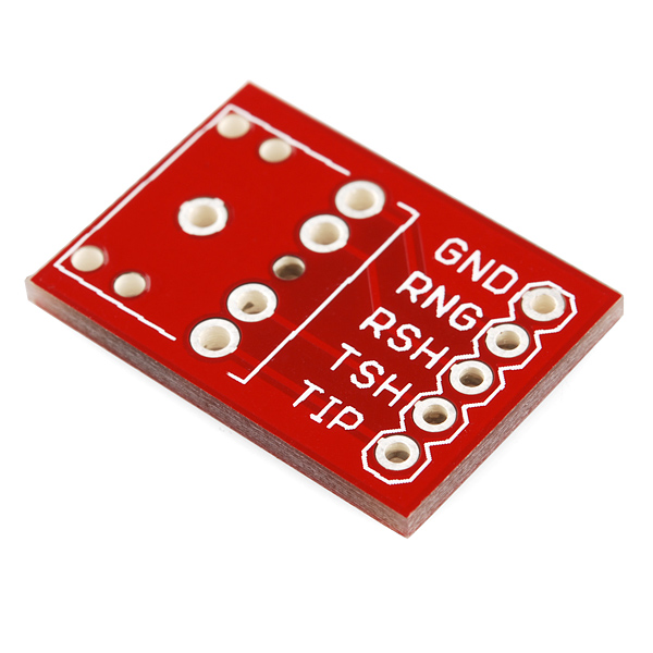
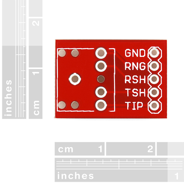
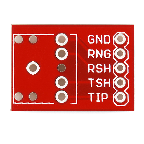
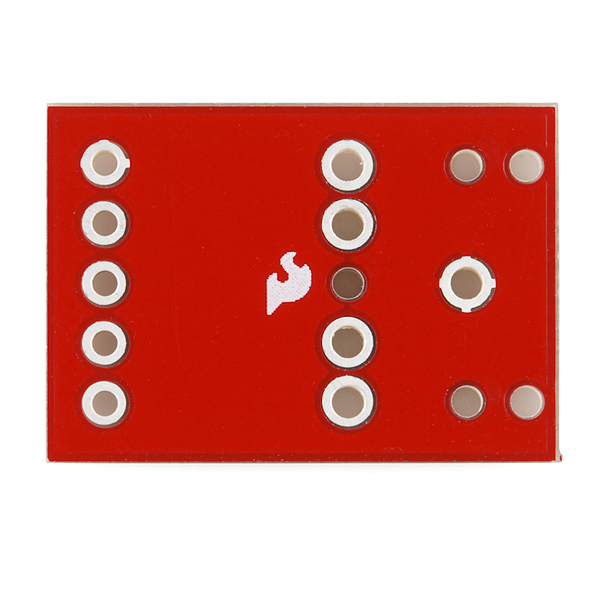
Simple breakout board for the 3.5mm audio jack. Use this breakout (shipped bare) to allow breadboard or SIP access to the super-common 3.5mm audio jack. All five pins are broken out.
Note: You get the bare PCB only, check below for the Audio Jack.
SparkFun Audio Jack Breakout Product Help and Resources
Connector Basics
January 18, 2013
Connectors are a major source of confusion for people just beginning electronics. The number of different options, terms, and names of connectors can make selecting one, or finding the one you need, daunting. This article will help you get a jump on the world of connectors.
TeensyView Hookup Guide
March 16, 2017
A guide to using the TeensyView OLED board to display text and graphics.
Audio Codec Breakout - WM8960 Hookup Guide
January 26, 2023
The SparkFun Audio Codec Breakout - WM8960 is a low power, high quality stereo codec chock full of features. In this tutorial, some of these features by using an Arduino microcontroller to configure the audio codec and pass audio to the headphone or speaker channels.
Analog MEMS Microphone (VM2020) Hookup Guide
February 9, 2023
Get started with the SparkFun analog MEMS microphone breakout board! In this tutorial, we will be connecting the differential MEMS microphone to an Arduino using the WM8960 audio codec.
Core Skill: Soldering
This skill defines how difficult the soldering is on a particular product. It might be a couple simple solder joints, or require special reflow tools.
Skill Level: Noob - Some basic soldering is required, but it is limited to a just a few pins, basic through-hole soldering, and couple (if any) polarized components. A basic soldering iron is all you should need.
See all skill levels
Comments
Looking for answers to technical questions?
We welcome your comments and suggestions below. However, if you are looking for solutions to technical questions please see our Technical Assistance page.
Customer Reviews
5 out of 5
Based on 1 ratings:
Yet another handy board
Although I fully intend to create my own PCBs in the long run it is nice to piece parts together with a breadboard until I'm ready to order. Took some time to understand the shunts are used for two reasons. 1. Reduce pop from plugging and unplugging when used with a capacitor. 2. Allow a headphone jack before the speakers.


You've got a 2.5mm cable and a 3.5mm jack listed as related products. Someone's not gonna be happy.
Just got this with the audio jack. Plan to use this just after the RN52 breakout(bluetooth audio) to add an aux port. Any comments as to if this is a bad idea?
Is there any schematic to formatting with an Uno?
To eventually use a Non-Invasive Current Sensor.
I am going to use these to replace the homebuilt Picaxe programmer breakout I built. For mine I simply added the two resistors the Picaxe uses on its Serin pin. The original was built on stripboard; but this will make for a cleaner adaptor once I add two SMD resistors to it- should be simple enough.
I find myself prototyping Picaxe projects on breadboard from time to time, and I found that such an adaptor really speeds up the process (I have never fully understood why the resistors are not simply built into the Picaxe's, since they are necessary for proper operation and programming.)
It would be cool if Sparkfun added the two resistors to this breakout and offered it as a Picaxe programming breakout, but I do not know if there would be much demand for it.
If you want to use this breakout to hookup a spare set of amplified PC speakers to a micro's 3.3-5V PWM or DAC output pin on a breadboard here is a schematic
A 10K:1K voltage divider is used to drop the voltage and a 1uf DC blocking capacitor is used. If it is a mono audio signal just tie the left and right stereo inputs together as seen in the schematic. Anything close to those R and C values will work, if you do not have the exact values.
Is it possible that these are labeled incorrectly, or that the previous (green) ones were? I have some of the old ones, which are labeled differently from these, and I can't get the new ones to work unless I wire them incorrectly, at least according to the code example on your BOB-09943 page.
I use my audio jack breakout on a breadboard, and put a 10K resister from the RNG to TIP, therefore eliminating the need to include it on the picaxe download circuit. It saves a little space on my picaxe boards.
Meant to reply to above
what do these names mean
Ground, ring, ring shunt, tip shunt, tip(thats from top to bottom in pic)
What do these names mean?