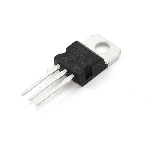
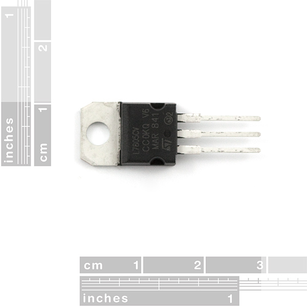
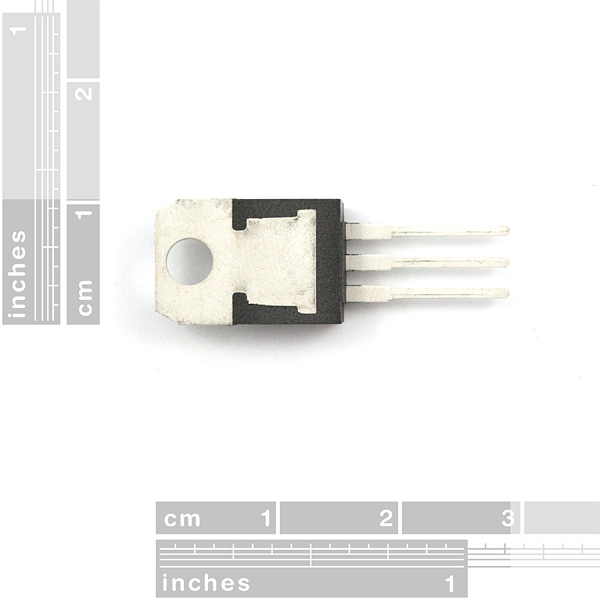
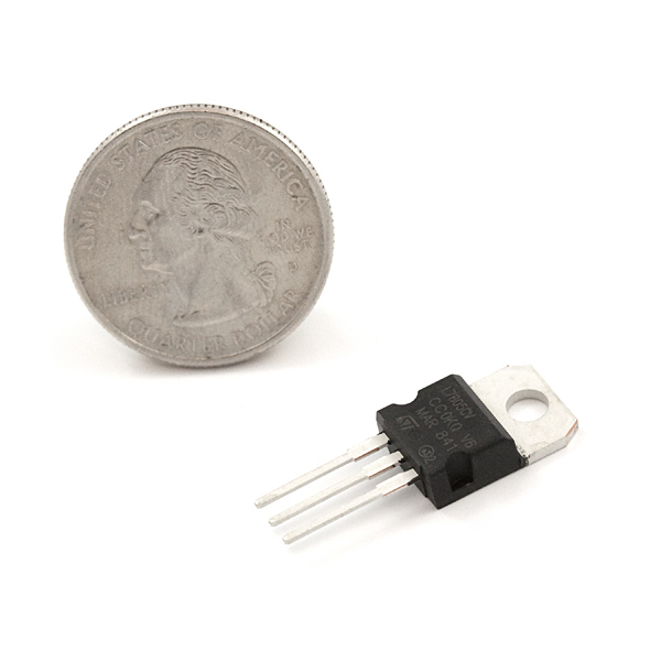
This is the basic L7805 voltage regulator, a three-terminal positive regulator with a 5V fixed output voltage. This fixed regulator provides a local regulation, internal current limiting, thermal shut-down control, and safe area protection for your project. Each one of these voltage regulators can output a max current of 1.5A.
- Output Voltage: 5V
- Output Current: 1.5A
- Thermal Overload Protection
- Short Circuit Protection
- Output Transition SOA Protection
Voltage Regulator - 5V Product Help and Resources
Boss Alarm
March 30, 2016
Build a Boss Alarm that alerts you of anyone walking into your office and automatically changes your computer screen.
Proto Pedal Example: Programmable Digital Pedal
September 22, 2016
Building a pedal around the Teensy 3.2 and Teensy Audio shield. Changing the effect in the pedal is as easy as uploading a new sketch!
Beginner Parts Kit Identification Guide
March 22, 2019
The essential parts for beginning (or even experienced) hobbyists that gives you all of the basic through-hole components you will need to get started playing with embedded projects. We'll identify a few parts in the kit and provide a few basic circuits to get started!
Magnetic Levitation
November 20, 2019
This tutorial will show you how to build a magnetic levitation circuit using common parts.
Resources and Going Further
For more information about methods of managing heat dissipation (using air, protoboard, copper PCB, heatsink, and heatsink + fan) with the 7805, try checking this enginursday post:
Or check out this example using a Raspberry Pi, RC LiPo battery, and TB6612FNG DC motor driver.
Core Skill: Soldering
This skill defines how difficult the soldering is on a particular product. It might be a couple simple solder joints, or require special reflow tools.
Skill Level: Noob - Some basic soldering is required, but it is limited to a just a few pins, basic through-hole soldering, and couple (if any) polarized components. A basic soldering iron is all you should need.
See all skill levels
Core Skill: Electrical Prototyping
If it requires power, you need to know how much, what all the pins do, and how to hook it up. You may need to reference datasheets, schematics, and know the ins and outs of electronics.
Skill Level: Competent - You will be required to reference a datasheet or schematic to know how to use a component. Your knowledge of a datasheet will only require basic features like power requirements, pinouts, or communications type. Also, you may need a power supply that?s greater than 12V or more than 1A worth of current.
See all skill levels
Comments
Looking for answers to technical questions?
We welcome your comments and suggestions below. However, if you are looking for solutions to technical questions please see our Technical Assistance page.
Customer Reviews
5 out of 5
Based on 3 ratings:
Hey, five volts!
Always handy to have a stable regulated supply for sensitive electronics. This is the best way to go!
Oldy and Goodie
This chip design dating from the 1970s is a quick and handy 5 volt regulator for just abut anything that needs a constant voltage supply up to about 1.25 amp. A heat sink is a good idea above about 200ma.
It's great to find these are still sold!
recommended.
Wonderful
Nothing really to say. Works like a charm!


I just found out that these Regulators will stop regulating somewhere between 7v and 7.5v. Trying to use a 9v battery with one of these is a mistake. I found this out the hard way driving a Pic and a 4D 1.44 ulCD display (these displays rock!). I have spent the last day trying to figure out why everything went wonky on me until I read about this.
What I have gathered is I need a low drop out (LDO) regulator to make this work. DigiKey has an LP2989IM-5.0-ND which supplies 5V/500mA with a drop out of .31v which allows for a lot better utilization of the 9V battery. I may eventually go with a LiPO option but the 9V fits my project well. The Display draws a maximum of 180mA and most of my display is black so it should be well less than the max. With a 9v supplying about 500mAh, I would be content to get about 3 hours of solid uptime with the PIC taking up essentially none.
Hope this helps someone in the future.
Definitely works above 7 volts, the data sheet specifies it will regulate up to 25V in. I have run a PIC18F452 with no heat at all from 9V in
He's not saying it won't run ABOVE 7 volts, he's saying it won't run BELOW it, and he's right; the datasheet specifies that this regulator has a 2V dropout, meaning that once your 9V battery drops to 7V, you won't be able to use this regulator anymore.
That is not true. This works with a brand new 9V battery. Doesn't even get that hot.
I was on Digikey and found this awesome replacement: V78xx Switching Regulators
91% efficiency?! OH MY GOODNESS! That's almost as efficient as a transformer!
A transformer is 0% efficient with DC.
I was saying that just as a comparison of efficiency, not that a transformer could ever replace switching or linear regulators in a DC circuit.
Transformers are also considerably less than 100% efficient.
Hmmm, I thought differently before and I don't know why... Thanks for the clarification!
Above 97% for higher voltage transformers seems pretty good to me.
:() AWESOMENESS
These would be a nice addition to the products here... hint hint... (they are kinda of expensive but not too bad for a drop in replacement)
I'm driving one with a 16V supply. I drilled a hole in a quarter and bolted it to the 7805, and it's been stable for at least 2 weeks.
You should keep in mind that the quiescent current on this is very high at around 5-10mAh depending on input voltage. I found out the hard way that it chews through batteries.
WARNING: Be sure to have correct polarity on this, otherwise it will get extremly hot very quickly. Melted my wires :).
Hello, I Have A Question. I Am Making A Littlebits Module for the Bitlab, Would This Work With The RadioShack® 0.5W Solar Panel 6V To Create A Solar Module.
Umm which one is this exactly in the Eagle library? Thanks!
This would be "78XXL" :) (there's one in SparkFun-PowerIC.lbr and one in the standard v-reg.lbr library)
thnx!
Really odd, I can barely get 0.5A through this thing. I have a motor that runs on 5V .5 amps directly from my desktop switching power supply just fine. I put this regulator in the way, crank the supply up to 9V and now the motor can only run in fits and starts if at all off the 5V regulated power. The regulator does not get to hot to touch but never seems to demand much more the .03A from the power supply. Is the datasheet correct on this?
These regulators make excellent heaters when used with reverse polarity. I used one with an Arduino and a thermistor to regulate the temperature of a jar of brine shrimp.
The data sheet doesn't quite match the item. For the most part they are the same, but the data sheet says it can handle up to 1.5 amps, whereas the actual 7805 SparkFun is selling burns up well before that. The data sheet is from Texas Instruments, but the product in the photo is made by ST Micro.
My project is drawing 300-400mA, and this ST-made 7805 is nearly too hot to touch (I measured it at over 45 degrees C), but when powering it using a 7805 made by TI (probably the same one in the data sheet) it barely got warm. Probably has a lot to do with the TI-made 7805 having a much beefier heatsink.
Warning: Do not use these with your Humble Pi! The polarity is way off!
^ If I had know that I wouldn't be soaking my finger in ice water. But here I am.
And as a lame pun. I have been forced to take a bite of humble pi. And a datasheet.
This is prob a noobish question but... If I wanted to lower the amount of heat this thing puts off, could I lower the input voltage with a voltage divider? And is this a smart idea? -Thanks in advance!
No, a voltage divider on the input will not work. And a series resistor on the input will dissipate some of the heat itself, but isn't recommended if you can avoid it. Best practices with these are: use an input voltage as low as possible (but not lower than Vout + 1.5V); use a heat sink (these will only reach full current output with a heat sink); and use a switching regulator if the situation calls for it.
Yes and no. You would be lowering the heat the regulator gives off, but now you're adding heat being radiated out by the resistor(s) even less efficiently. A series resistor (depending on application, would be fairly high wattage) would be more efficient, but will still be getting hot. The packages for these resistors can dissipate that heat more easily, though (hint: they're physically big), to the point of being able to used without a heatsink at all. They're available fairly cheaply, but the down side is the extra space required and that you're still wasting energy.
If heat is a concern and you can't implement a lower voltage input to begin with (what is your use case?), you could try designing a circuit using a switching regulator. There are drop-in replacements for the LM7805. They are a fair bit more expensive, and can be RF-noisy, but as long as that's not an issue or can be designed around, they may be an appropriate replacement as they are vastly more efficient, meaning they waste a lot less energy as heat.
O.K. Thanks for the info! I'll see if I can get a series resistor to work and I'll order a couple switching regulators (for the future and whatnot). As far as my set up goes: I have a breadboarded ATmega328p, with a (https://www.sparkfun.com/products/10533) receiving RF, they are currently both on the 5v reg power. You said that a switching regulator causes a little RF noise, do you think it would be enough to cause an interference at 315MHz? As far as dropping the input voltage, I have tried using a 5v 1A power supply (I think this was it: https://www.sparkfun.com/products/8269) and removing the regulator, but then the Mega gets warm (Checking for shorts =P). Also I am worried that the ATmega won't like the 5v directly from the power supply (would powering it directly like that be fine?). Once again, thanks a bunch for the help!
Sorry, didn't catch the reply notification on this one. I'm afraid I don't have nearly enough experience to know whether it would interfere with equipment on 315MHz - that would largely depend on the switching frequency, how sensitive the equipment is on harmonics, and of course the actual design of the device incorporating the switching regulator.
I don't think the Mega is supposed to get warm, but it should be fine with the 5V; double-check the datasheet for the acceptable input voltage range and what that might affect, though :)
This may be a little out there, but can run these in parallel to up the amperage? If put 10 of these with the proper decoupling caps in parallel, could I theoretically run something at 10 amps? The main reason I ask is that 10A VR's can run between $50-$100 and I figure this can be a cheap alternative for some basic regulation on my solar setup.
The quick answer is that you can try, however slight manufacturing differences will typically mean that one device will try to handle most of the load, shut down, with the same thing happening to the rest in sequence. Google "parallel voltage regulators" for more information.
But, you should be able to find or make a 5V 10A voltage regulator for much less than $50, especially if it can be a nonisolated switching DC-DC type rather than a linear regulator.
I'm trying to get a stable 5v output from a 600mA 12V wall plug that also runs a small amp for a portable stereo I'm building eventually I will upgrade to a 2A supply what would you reccomend.
how can i calculate the capacitor needed in my system ? i want to power a attinny from a 12v 2A led strip power supply , and use the attinny as the controler for the strip . is the capacitor value really important ? or anything between 0.1 to 10 uF will do ?
will it be really hot , heat wise ? should i use another regulator ?
Using between 1-10uF is common. As for the heat, you may have to use a heatsink being that it is using a 12V source. What kind of current draw will your ATtiny setup use?
heu.. i guess not much , i just use it to read a analog pin , and set a Hight or Low pin to drive this guy http://www.sparkfun.com/products/10256 i hope i am doing it right
Then you easily be able to use this regulator.
nice ! thank you .
So can I use this if I have an 12v analog signal? I want to connect it to IOIO for android DEV-10748.
Which caps should I use with this regulator? If I want a realy stable supply?
In the data scheet they use a 0.33 uF and 0.1 uF.
And here http://www.arduino.cc/en/Main/Standalone are they useing 2 10 uF capacitors.
I'm speculating here, but I think the best capacitance depends on how much current you need to supply. If your capacitance is too low compared to your current, then your supply wont be stable, but if the capacitance is too high compared to your current, then you wont be able to charge the caps up to the right voltage.
I use a standard circuit which has the 7805, a 10uF on Input and 1uF on output. Most of these different capacitor setups will work most of the time.
AFAIK The difference in power entering and leaving these things is dissipated as heat. Most of these things can only dissipate so much (7805A maxes out at 2.7W) Which means that although you can feed them 25V, you limit the current you can pass through unless you've got some wacky cooling.
On a recent project, I had mine cooled to -85°C with LN2, had about 8 to 10 watts and it worked fine ;) Does that qualify as wacky cooling?
Yes. LN2 counts as wacky 80% of the time :)
Tried supplying it with 4 AA batteries (6v) but it will not output 5v then. So if you plan power your project with batteries using this then go for 9v. Or just drop the regulator and use the "NCP1400-5V Step-Up".
The minimum supply voltage is 7 volts, and the maximum is 25 volts. It says so in the datasheet. From experience I know that the performance will be eractic when supplying it lower than 7 volts.