Arduino Pro 328 - 3.3V/8MHz
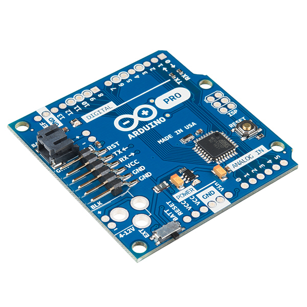
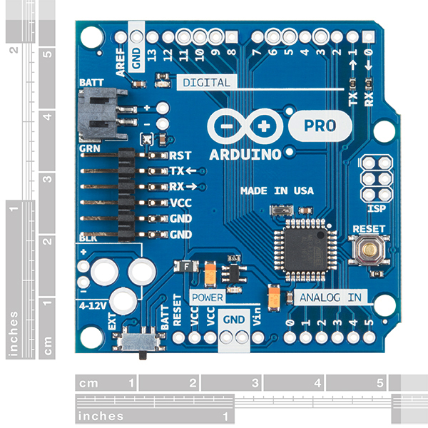
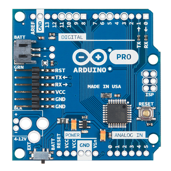
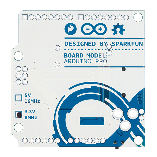
It's blue! It's skinny! It's the Arduino Pro! SparkFun's minimal design approach to Arduino. This is a 3.3V Arduino running the 8MHz bootloader. Because the system voltage for this board is lower than other Arduino development boards, it may not be compatible with many Arduino shields which were designed to run at 5V. The Arduino Pro 3.3V still works great with our prototyping shield so you can create your own 3.3V shields. The lower system voltage also has its advantages, like ease of use with many common 3.3V sensors.
Arduino Pro does not come with connectors populated so that you can solder in any connector or wire with any orientation you need. We recommend first time Arduino users start with the Uno R3. It's a great board that will get you up and running quickly. The Arduino Pro series is meant for users that understand the limitations of system voltage (3.3V), lack of connectors, and USB off board.
To keep things affordable and low profile, we've chosen to make the DC power jack footprint available, but not to populate it. We recommend running the board with a LiPo battery for better portability. Also, to keep the cost low, we made changes like using all SMD components and switching to a two layer PCB.
This board connects directly to the FTDI Basic Breakout board and supports auto-reset. The Arduino Pro also works with the FTDI cable but the FTDI cable does not bring out the DTR pin so the auto-reset feature will not work. In this latest version of the Arduino Pro we've also moved the FTDI headers back* just a skoach* so that the pins don't hang over the edge of the board. We've also populated it with a sturdier power selection switch.
Not sure which Arduino or Arduino-compatible board is right for you? Check out our Arduino Buying Guide!
**Note: **A portion of this sale is given back to Arduino LLC to help fund continued development of new tools and new IDE features.
Replaces:DEV-09221
- ATmega328 running at 8MHz external resonator
- Low-voltage board needs no interfacing circuitry to popular 3.3V devices and modules (GPS, Accelerometers, sensors, etc)
- USB connection off board
- 3.3V regulator
- Max 150mA output
- Over current protected
- Reverse polarity protected
- DC input 3.3V up to 12V
- Resettable fuse prevents damage to board in case of short
- Power select switch acts as on/off switch
- 2.1x2.05" (53.34x52.08mm)
Arduino Pro 328 - 3.3V/8MHz Product Help and Resources
Choosing an Arduino for Your Project
December 11, 2017
Examining the diverse world of Arduino boards and understanding the differences between them before choosing one for a project.
Core Skill: Soldering
This skill defines how difficult the soldering is on a particular product. It might be a couple simple solder joints, or require special reflow tools.
Skill Level: Rookie - The number of pins increases, and you will have to determine polarity of components and some of the components might be a bit trickier or close together. You might need solder wick or flux.
See all skill levels
Core Skill: Programming
If a board needs code or communicates somehow, you're going to need to know how to program or interface with it. The programming skill is all about communication and code.
Skill Level: Rookie - You will need a better fundamental understand of what code is, and how it works. You will be using beginner-level software and development tools like Arduino. You will be dealing directly with code, but numerous examples and libraries are available. Sensors or shields will communicate with serial or TTL.
See all skill levels
Core Skill: Electrical Prototyping
If it requires power, you need to know how much, what all the pins do, and how to hook it up. You may need to reference datasheets, schematics, and know the ins and outs of electronics.
Skill Level: Competent - You will be required to reference a datasheet or schematic to know how to use a component. Your knowledge of a datasheet will only require basic features like power requirements, pinouts, or communications type. Also, you may need a power supply that?s greater than 12V or more than 1A worth of current.
See all skill levels
Comments
Looking for answers to technical questions?
We welcome your comments and suggestions below. However, if you are looking for solutions to technical questions please see our Technical Assistance page.
Customer Reviews
5 out of 5
Based on 1 ratings:
3.3v and Form Factor make this extremely valuable
I've been working on weather stations and other low power IoT devices, and the 3.3v version of the Arduino has been very helpful for testing and prototyping. Probably the most valuable part of this board though is that the form factor is similar enough to be compatible with the vast majority of Arduino shields.


This seems rather obvious with the 5/3.3V silkscreening under the header, but just to be absolutely certain: I can safely program and operate this with a 5V FTDI without risking damage to the board, right? And likewise, if I've got it plugged into my computer over the FTDI cable, the voltage from the I/O pins will be safe for 3.3V devices even if the board itself is running from 5V USB over the FTDI connection?
Sorry, just saw this comment. Yes, the only differences between the 5V and 3.3V are the value of the voltage regulator and the value of the crystal. The ATmega328 is fine with a VCC of either value and the FTDI line is VCC and therefor bypasses the voltage regulator. The only thing that might be iffy is that 3.3V/16MHz is technically out of spec. We actually run boards at that voltage all the time without a problem, but if you starting trying to go lower and run it at 1.8V or something you will likely run into problems.
As for the second part that is not correct. Because the FTDI is connected directly to VCC and does not go through the regulator the chip will be running at 5V and therefor the I/O pins will be running at 5V. Be careful if you do this of powering anything from VCC (which is tied directly to the power from the FTDI) and of anything sensitive to 5V from the I/O pins.
I am having trouble programming this board. Using just the "Blink" example, when I click on the Upload button, the Arduino IDE indicates that it has started uploading, but then I get a series of avrdude: stk500_recv() and avrdude: stk500_getsync() errors.
I have both an USB-FTDI adapter and a USB-PL adapter, and both return the same error (I know for sure that both adapters work because I've used them with ESP8266s and other Arduinos).
I've double-checked every setting I can think of:
The red power LED on the board is lit.
I can post the verbose output of the Upload attempt if needed.
Thanks for your help.
SOLVED!: Turns out that I merely need to hold the RESET button down during compilation of the sketch and then release it when the UPLOADING message appears in the status area.
That is a pretty standard error which generally means the IDE can't find the bootloader it is looking for. This means there are quite a few reasons things aren't working (FTDI drivers, wrong COM port, wrong board selected, etc.) These boards should have autoreset built in (on the DTR line) meaning you shouldn't have to hold down the reset, if that is the case something might be wrong with your board. First thing I noticed is that you have the processor set to 5V/16MHz, for this board you want 3.3V/8MHz. While you can get it to compile and upload at 16MHz all functions that are time based will be off (delay, all serial communication, etc.). If you are still having problems try sending techsupport an email and they should be able to help you out.
Thanks, I should pay closer attention to the product page on which I am posting.
It looks like I should connect the FTDI board's DTR to the RST line so that I don't have to hold the reset button?
Yes, the 6 pin header on the board is designed to plug directly into our FTDI boards which connect power, gnd, rx,tx and dtr (to reset). Once that is done you should have autoreset.
Do the mounting holes on the Pro match up to the holes on the original Arduinos? I want a 3v Arduino that can be solidly mounted to a standard shield, but to my eyeballs the holes near the power connector don't match.
If I made custom shields, perhaps I could put both holes in my shield so it would work with either Arduino?
Any advice would be appreciated. Thanks!
Yes they do. The outline of the Pro is slightly smaller but the mounting holes are in the same place.
When it says "3-12 volt input," does that mean you can power it with 3-12 volts, or that that's the acceptable range for the DC inputs?
Applies to raw power pins (battery / barrel jack) only. Inputs must not exceed VCC.
Personally I'm trying to determine if this is the regulator (rumored in another forum): http://dlnmh9ip6v2uc.cloudfront.net/images/products/10914-01.jpg
I am relattvely new to Arduino. Where do I tell the I/O subsystems that the system clock is 8MHz? Currently I am fudging the baud setting.
When using the Arduino IDE you just need to select the correct board. In this case the Pro Mini 3.3V/8MHz w/ATMega328 option. This board selection tells it what clock setting as well as other things like the actual chip, etc., to use when compiling.
Is it 3.3-12V input or 4-12V input? I have a 3.3V supply. Is that enough to power it?
The board has an OSHW emblem printed on it but the product page seems to be missing it up top? And the 5V version has the opposite: the emblem is listed on the product page but it isn't printed on the board. Just a little confusing...
They are both OSHW boards. Sorry about the confusion. Once we get our system up and running again, we can get this fixed to make it more clear.
I thought the Arduino Day deals were going to allow backorders? Disappointed!
Yes, what is up with that???
They responded on the arduino day thread, technical issue, they're looking into it.
I want to purchase this product, no SPI library? SPI must use this feature ......
.SPI: 10 (SS), 11 (MOSI), 12 (MISO), 13 (SCK). These pins support SPI communication, which, although provided by the underlying hardware, is not currently included in the Arduino language.
Not quite sure where you got that information, but SPI works just fine on these, both from the SPI library, and the serin/serout commands.
LMB Heeger makes a plastic enclosure that works well with this board. Part # PT 101. Perhaps SparkFun should carry them.......
Since this board has the 328, does it have a full 2kB SRAM (as compared to the Pro Mini at 1kB)?
Yes it has 2kB of RAM. But the Pro Mini has the same MPU, so it also has 2kB of RAM...
I take this does not have a battery charger on board?
Also why are all 3.3v arduinos 8mhz, instead of 16?
Nope, no battery charger on this board. The Fio has one though.
If you look at the Atmel datasheets, you'll find a graph in the back with the safe area for voltage vs. clock speed. The lower the voltage, the slower the clock must be to keep everything running correctly. At 3.3V, 16MHz is outside the safe area, but 8MHz is inside it. (Fun fact: you can run a 328 at 1.8V if the clock is 4MHz. The more you know!)
Thanks for the info. I've been looking for "inexpensive", and I want to make a number of boards for my project. I suppose if I'm making my own board, the cheapest thing is to make my own Arduino circuit.
I also want to be able to run off a lipo, but I'm also running an led matrix, which most controller chips for led matrix's are 5 volt (though the led matrix itself wants something like 2.7 volts.)
Choices, choices...
Do you have the part number of the SMD crystal? It seems that you don't have it for sale and I can't find it in Digikey. Thanks in advance
Found it! The crystal is the CSTCE16M0V53-R0 from Murata, DigiKey PN 490-1198-1-ND.
If you install the DC power jack, the FTDI Basic Breakout will not fit, unless you extend the pins with an Arduino stackable header.
This is not just for the "pro", it's also great for the "duffer" who doesn't want to be bothered with level shifters.
We changed the dimension of most of our FTDI basics(except the Lilypad FTDI basic, currently) to fit the Arduino Pro with the barrel jack connected. If you have a old FTDI basic and the PCB is wider then the black 6 pin header, the above fix would be required.
Hey Sparkfun, whats up with the buzzer pad between D4 and D5 on the board & in the schematic files? Somekind of easter egg? :-)
What is the purpose of the resistors on D0 and D1 (RX and TX)? These are only on the Pros, and not on the regular Arduinos or the Pro Minis. I have had to remove and jumper them on previous projects. Thanks.
Sorry for the late response.
The purpose of the resistors are to protect the pins from over current, given a case of two outputs connected together and one goes high, while the other goes low, i.e. short to GND.
For example, when you have two serial devices (FTDI and UART peripheral) connected to the atmega, they all share one set of TX and RX. You only need one resistor "blocking" the TX lines from the FTDI and external UART peripheral going to the atmega RX line (we really don't need both). Draw this out if this doesn't make sense. On this board, the resistor blocks the external UART peripheral from the atmega, while the arduino deumilanove, blocks between the FTDI and atmega. Either way, both prevent over current from happening between two TX lines.
Also, if you are needing to short across the resistors to get something to work, you probably have 3 UART devices connected together and you could have two outputs connected, so be careful. But sometimes this configuration can be useful, only in one direction of communication. Ideally, you want to use NewSoftSerial to move your peripheral UART device to another set of pins.
Hope this helps.
will the barrel jack charge the lipo?
Nope. No charge controller on this board. Try One of these or add a charger.
Shame this has missed out on the mew IOREF, SDA, SCL and Mystery pins on the new R3 Arduinos