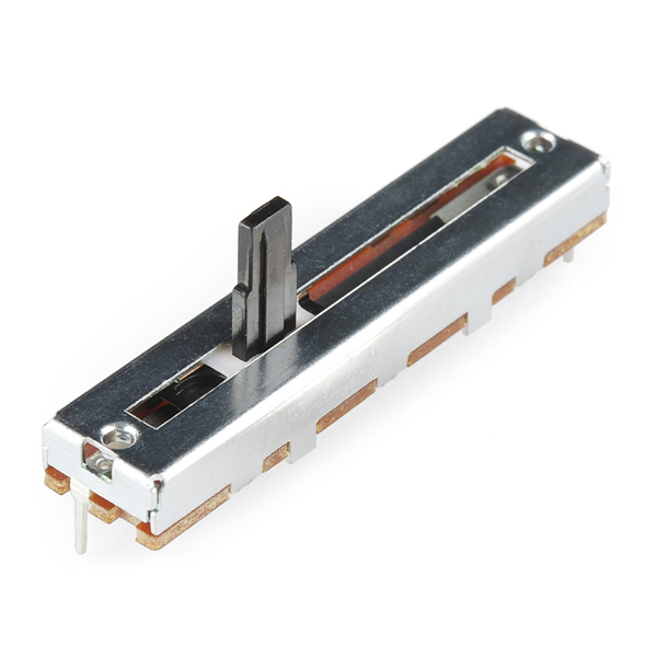
Slide Pot - Medium (10k Linear Taper)
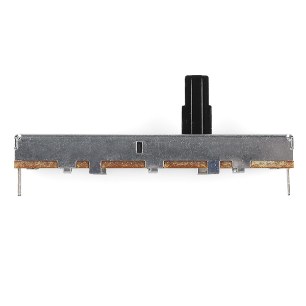
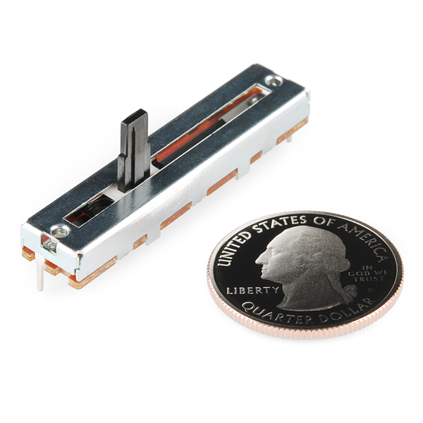
A simple slide potentiometer can go a long way. Rated at 10KOhm and 0.1W. Comes with solder tab connections. The pot has an overall travel of 30mm and has two mounting holes on top.
- 9.5mm x 45mm
- Datasheet (C3031N-1A2-B10K-GP)
Slide Pot - Medium (10k Linear Taper) Product Help and Resources
Core Skill: Soldering
This skill defines how difficult the soldering is on a particular product. It might be a couple simple solder joints, or require special reflow tools.
Skill Level: Noob - Some basic soldering is required, but it is limited to a just a few pins, basic through-hole soldering, and couple (if any) polarized components. A basic soldering iron is all you should need.
See all skill levels
Comments
Looking for answers to technical questions?
We welcome your comments and suggestions below. However, if you are looking for solutions to technical questions please see our Technical Assistance page.
Customer Reviews
4 out of 5
Based on 2 ratings:
1 of 1 found this helpful:
Works as expected. Can't mount it though.
The pot works as expected. As mentioned in the comments there is no pinout diagram on the datasheet, though it was very easy to determine which pin does what by using a multimeter.
The datasheet also states that the two mounting holes are for M2 screws. I've tried various screws, even went out to buy a specific M2 kit from a local electronics store but they don't work. It looks like the 4 pots I ordered aren't even threaded to accept a screw. A little disappointed by this.
UPDATE: I bought an inexpensive tap and die set and tapped the holes to M3x0.5 screws. Cuts close to the outer edge of the pot, but at least I can mount it now.
Sorry to hear about these issues with the threading. We will contact our supplier to see if they can correct this issue for future parts that they send us.
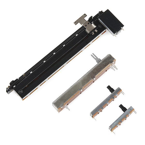
Knobs sold here don't work with this or the SMALL
Just an FYI, the only knob sold on SparkFun does not fit onto this slide pot. As you can see, this is a plastic post with some beveling on the sides. That beveling cracks the plastic mount on the knobs sold on SparkFun. You'll have to find other pots or knobs.
Also, if it's helpful, top singular pin is the ground, left bottom is voltage and right bottom is the signal.


Is this compatible with the slide potentiometer knob sold on here? https://www.sparkfun.com/products/9120
Is there an eagle .lbr file for this item? The data sheet doesn't seem to even say which pin is which.
If there was a little more information, especially a pin out chart like #93814 said that would be really helpful and I'd be very grateful... Making these things become guesswork is never really my ideal plan of action.
Pot works great. Used a meter to figure out which pin did what. Having a hard time finding the M2 screws for mounting though.
Would this fit onto a breadboard?
If these are the same as in the Danger Shield - and I suspect they are - then no, not without slightly snipping the leads / temporarily soldering some breadboard-friendly leads on top of the ones it has / wire-wrapping. The leads are too wide for a typical breadboard with 0.8mm max lead diameter.
I think I just wired this thing up wrong, even after checking everything with a meter. A pin diagram is really needed.