SparkFun USB Type A Female Breakout
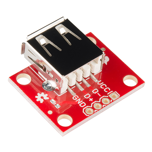
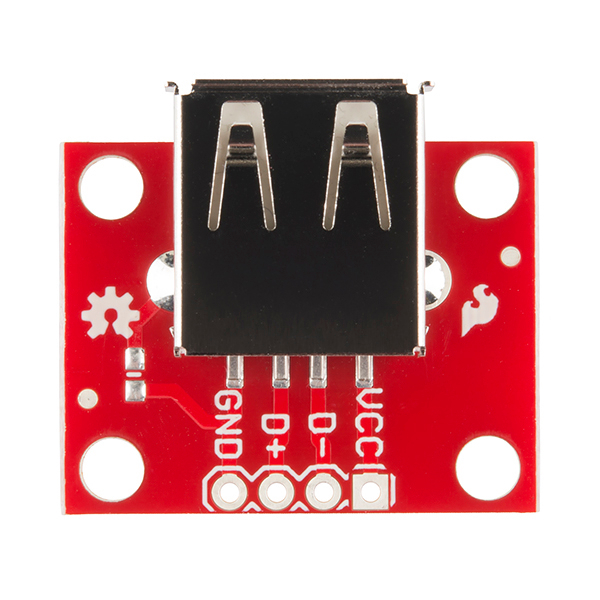
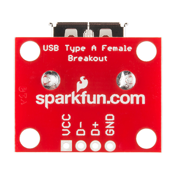
This simple board breaks out a female USB type A connector's VCC, GND, D- and D+ pins to a 0.1" pitch header. If you want to add a USB to your project, but don't want to put up with soldering tiny connectors, this is the board for you.
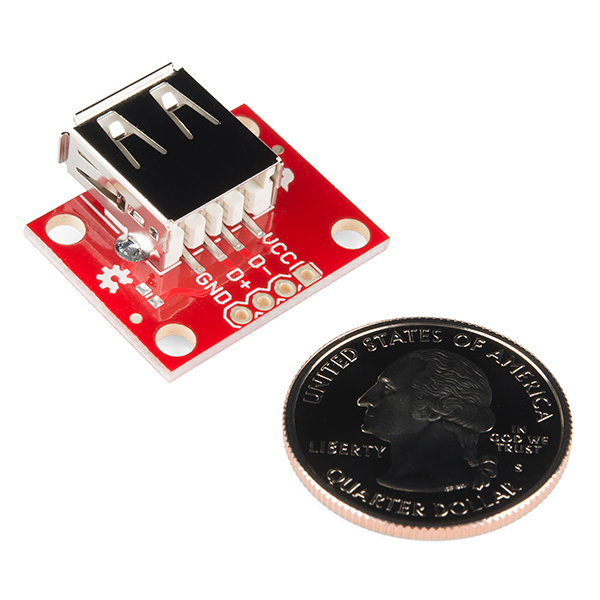
Dimensions: 1.02 x 0.9" (26.06 x 22.93mm)
SparkFun USB Type A Female Breakout Product Help and Resources
Connector Basics
January 18, 2013
Connectors are a major source of confusion for people just beginning electronics. The number of different options, terms, and names of connectors can make selecting one, or finding the one you need, daunting. This article will help you get a jump on the world of connectors.
USB Type A Female Breakout Hookup Guide
February 13, 2014
An above-and-beyond example using the USB Type A Female Breakout board.
WiFi Controlled Robot
May 2, 2018
This tutorial will show you how to make a robot that streams a webcam to a custom website that can be remotely controlled.
Qwiic Digital Desk Sign with MicroMod
June 30, 2022
Make a Qwiic-enabled digital desk sign with a MicroMod SAMD51 Processor Board's USB Host and a USB keyboard!
Core Skill: Soldering
This skill defines how difficult the soldering is on a particular product. It might be a couple simple solder joints, or require special reflow tools.
Skill Level: Noob - Some basic soldering is required, but it is limited to a just a few pins, basic through-hole soldering, and couple (if any) polarized components. A basic soldering iron is all you should need.
See all skill levels
Comments
Looking for answers to technical questions?
We welcome your comments and suggestions below. However, if you are looking for solutions to technical questions please see our Technical Assistance page.
Customer Reviews
4.7 out of 5
Based on 6 ratings:
1 of 1 found this helpful:
Works great and made my project more reliable.
I used this in a Digital readout box for my milling machine, very nice quality and went in fine. Very happy with the cards.
1 of 1 found this helpful:
Works as advertised
This was easy to solder and use.
makes life easier
I use these for the master side of TWI communication, with a micro USB on the slave side. No way to mix up sda/scl, and everything is connected by easy-to-find phone cables, eliminating the ridiculous amount of wiring I used to have. As a bonus, the Fritzing part already exists... I didn't have to spend a full work day drawing. I just make the document and move on.
Don't prototype without it.
In every hobbist's kit there are some basic necessities that you just have to keep in stock. This is one of them. I have quite a few PocketBeagles that don't come with host connectors, and I just need to use that WIFI dongle. Don't forget to twist those differential pairs!
Handy USB connector
Makes it much easier to add USB power & data to your project, screw holes are great extra, and that connector pin outputs are labeled clearly and on both sides. Also, there is place for small SMD capacitor or similar. Comes with USB connector pre-soldered Price is good, considering quality, and this makes projects much easier & professional look


What is the vertical dimension for this part? I will be mounting 4 in a tight spaces and need to properly space them. If Eagle Files shows it, I can't figure out how to rotate the view so see.
USB connector is 6.8 mm in height (from top of PCB to top of part). The flanged opening of the USB port is 7.1 mm. Max height (bottom of USB clips sticking out the bottom of the board to top of flanged opening) is about 11 mm (the clips can be bent or cut off).
Would there be any chance of you guys getting a usb 3.0 version of this?
It would be very helpful if you would add mounting dimensions for your products. That way mounting development could be figured in while waiting for an order to arrive.
Some of the products have 3D models made for them. Additionally, you can look at the EAGLE files to get these dimensions. For this board, the holes are 0.13" diameter and are placed 0.8" and 0.6" away from each other.
How much current can pass through it? I need 1 - 3 amps.
Looks like it's rated for 1.5 A: http://www.4uconnector.com/online/object/4udrawing/18666.pdf. Definitely make sure the wires in your USB cable can handle that, too.
Thanks! I needed a way to control a USB powered fan with an arduino.
If I have a + - circuit where the - is grounded. To which vcc d- d+ gnd, do I connect my circuit + and - to? Its a 5v 1a circuit
d+ and d- are the data lines. To supply power, (and I'm guessing that you mean + and - are used to power your circuit) + goes to vcc and - goes to gnd.
Can anyone tell me other dimensions on this board? How thick the PCB is, how far off the board the center of the USB port is.. I'm trying to CAD something up before these arrive and are in my hand. Seems like some of the available files above would give me that info, but I have a MAC so can't open them.
EAGLE will run in a Mac: http://www.cadsoftusa.com/download-eagle/?language=en which will let you look at the board files. The boards are 0.062 inches thick. Hope that helps.
I'd ideally need the side profile as well as the provided top view. I'll be getting the parts in soon, just trying to get a jump on a project for production. The USB port appears to bump out from the board a little, I need that little measurement to be sure everything lines up. Thanks for your help thus far.
Does anyone know if the BREAK AWAY MALE STRAIGHT HEADERS will fit into the VCC/D+/D-/GND through-hole solder points? What I would like to do is break off a section of 4, and solder them on so that I can make this breadboard-able. Thanks!
Yes, the break away male straight headers will fit into the VCC, D+, D-, and GND holes. Both the holes and the header pins have a 0.100 inch pitch.
GREAT! That's great news. I figured they would fit but I wanted to be sure. I just placed my order - can't wait! I'm adding an auxiliary USB port to my iHome and am in the final stages of prototyping so this will be perfect.
salve, any ideas about availability ?