SparkFun Current Sensor Breakout - ACS723
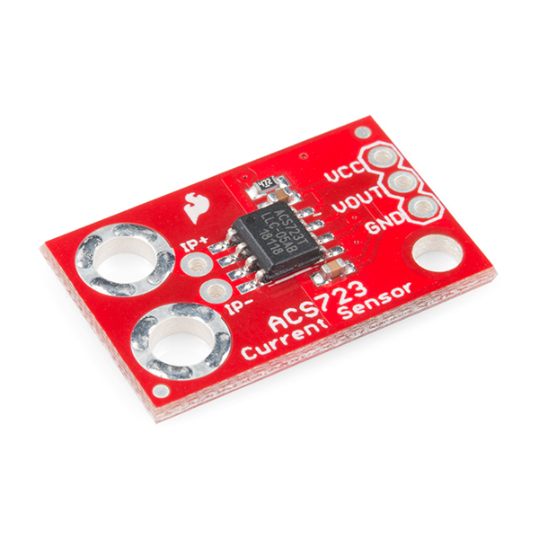
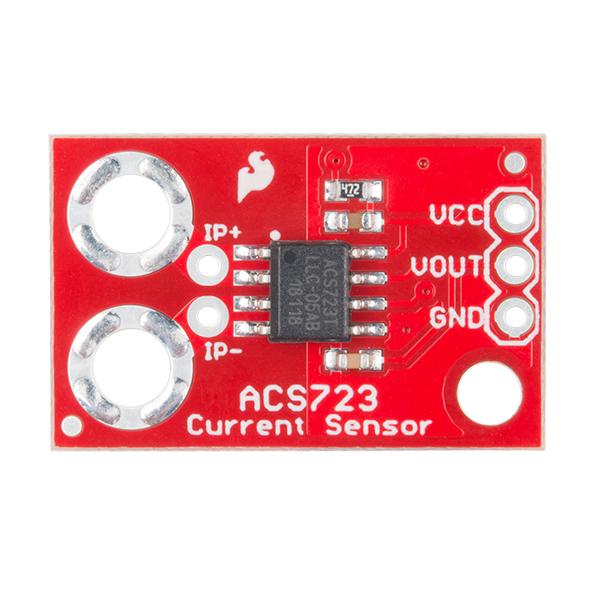
The SparkFun Current Sensor Breakout is a high accuracy board that utilizes the ACS723 for moderate AC and DC current sensing applications. The ACS723 sensor uses a Hall effect sensor to output a voltage relative to the current flowing through the IP+ and IP- pins on the board. The advantage of using a Hall effect sensor, specifically, is that the circuit being sensed and the circuit reading the sensor are electrically isolated meaning that, although your Arduino is running on 5V, the sensed circuit can be operating at higher DC or AC voltages!
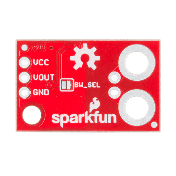
The SparkFun Current Sensor Breakout measures both DC and AC currents all the way up to 5A, has full electrical isolation of measured and sensed circuits, and has a base sensitivity of 400mV/A. Although the analog output is adjustable to 80kHz, the bandwidth on the ACS723 Sensor Breakout width filter has been set to 20kHz to reduce noise when using at high gains. The full 80KHz bandwidth that the sensor is capable of can be recovered by closing the JP1 (Bandwidth Select) jumper on the back of the board.
Note: Although the chip itself is rated for up to 2.4kV (RMS) of isolation, the board has not been designed for such high voltage applications.
- Schematic
- Eagle Files
- Hookup Guide
- Datasheet (ACS723)
- GitHub
SparkFun Current Sensor Breakout - ACS723 Product Help and Resources
Current Sensor Breakout (ACS723) Hookup Guide
June 21, 2018
Learn how to measure the current consumption of your project using the ACS723 Current Sensor.
Core Skill: Soldering
This skill defines how difficult the soldering is on a particular product. It might be a couple simple solder joints, or require special reflow tools.
Skill Level: Noob - Some basic soldering is required, but it is limited to a just a few pins, basic through-hole soldering, and couple (if any) polarized components. A basic soldering iron is all you should need.
See all skill levels
Core Skill: Programming
If a board needs code or communicates somehow, you're going to need to know how to program or interface with it. The programming skill is all about communication and code.
Skill Level: Rookie - You will need a better fundamental understand of what code is, and how it works. You will be using beginner-level software and development tools like Arduino. You will be dealing directly with code, but numerous examples and libraries are available. Sensors or shields will communicate with serial or TTL.
See all skill levels
Core Skill: Electrical Prototyping
If it requires power, you need to know how much, what all the pins do, and how to hook it up. You may need to reference datasheets, schematics, and know the ins and outs of electronics.
Skill Level: Competent - You will be required to reference a datasheet or schematic to know how to use a component. Your knowledge of a datasheet will only require basic features like power requirements, pinouts, or communications type. Also, you may need a power supply that?s greater than 12V or more than 1A worth of current.
See all skill levels
Comments
Looking for answers to technical questions?
We welcome your comments and suggestions below. However, if you are looking for solutions to technical questions please see our Technical Assistance page.
Customer Reviews
4.7 out of 5
Based on 3 ratings:
2 of 3 found this helpful:
Excellent!
Board is excellent for measuring current & is priced well - the chip alone costs 8.5$ CAD on digikey. Another version of this board has a 3star review due to low resolution - just want to say that this is unfair, this is an analog device so you are limited by the resolution of your ADC - on the arduino this is 1024 steps over 5V. if your readings are too jumpy, average them out or use a low pass filter. great product!
I must be missing the boat...
I was attempting to use the SparkFun ACS723 to measure AC current. My hope was to provide an alarm point at .75 Amps RMS. It appears that while measuring AC current, the ACS723 provides an output of 400 mv. AC. per measured AC amp. I was hoping that its output would be a DC voltage that could easily be fed into a comparator to provide an alarm point. What would one do with 400 mv. AC per amp? 400 mv. isn’t enough to bias a silicon diode to saturation as a rectifier so the signal would need to be amplified. More circuitry… Am I missing the boat? What is so wonderful about the SparkFun ACS723? I purchased a product on Amazon that used a current transformer and set point potentiometer. That module provided a relay closure at set point for $8.95. It works great! I must be missing the boat… I would like to see a schematic to work around my problem. Thanks


Hello, I have a spindle motor for a DIY engraver that is 100V and 500W so 5 Amps? Would this board be able to handle the 100VDC? I'd really like to measure the current since one of our motors likes to stall out, I plan on killing the power to the motor if the current rises to high. Thanks
Comparing the schematic with the board's image, ehe capacitor and the resistor are changed. C3 and C4.
This board is not suitable for 120v or 240v as the ground pour under the chip is too close to the input side for proper isolation.