SparkFun I2S Audio Breakout - MAX98357A
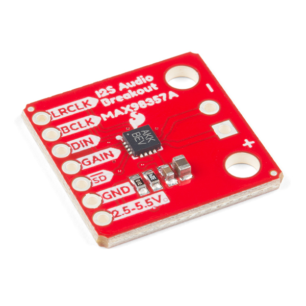
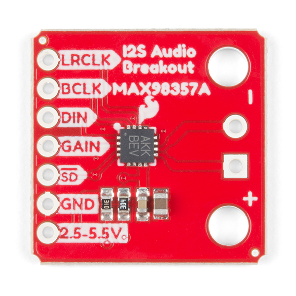
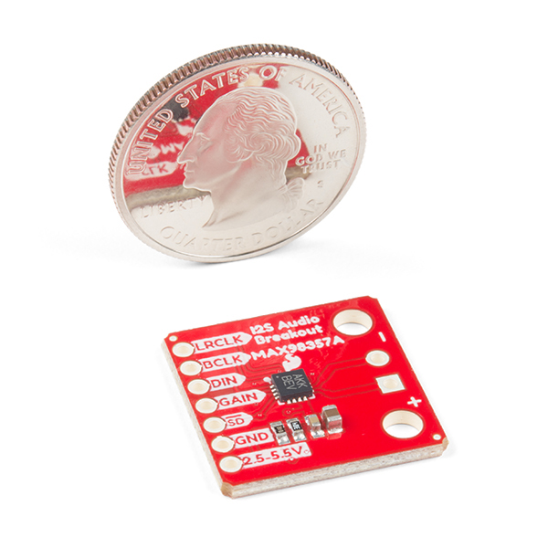
The SparkFun I2S Audio Breakout board uses the MAX98357A digital to analog converter (DAC), which converts I2S (not be confused with I2C) audio to an analog signal to drive speakers. The I2S Audio Breakout converts the digital audio signals using the I2S standard to an analog signal and amplifies the signal using a class D amplifier which can deliver up to 3.2W of power into a 4Ω load. The board can be configured to output only the left channel audio, right channel, or both.
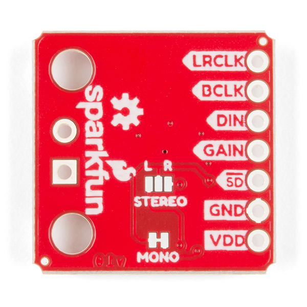
The SparkFun I2S Audio Breakout board is fairly simple, requiring only a few pin connections to get it up and working. By default the board is configured in “mono” operation, meaning the left and right signals are combined together to drive a single speaker. If you want a separate speaker for the left and right audio channels you’ll need to cut the mono jumper. In addition to being able to select the audio channel output, the gain can also be configured in a few ways. The gain of the amplifier can be configured from as low as +3dB to as high as +15dB. While the channel selection can be configured on board, the gain however is controlled externally using the gain pin. By default, the board is configured for +9dB, but can be easily changed!
- Supply Voltage Range: 2.5V - 5.5V.
- Output Power: 3.2W into 4Ω at 5V.
- Output Channel Selection: Left, Right, or Left/2 + Right/2 (Default).
- Sample Rate: 8kHz - 96kHz.
- Sample Resolution: 16/32 bit.
- Quiescent Current: 2.4mA.
- Filterless Class D Outputs
- No MCLK Required
- Click and Pop Reduction
- Short-Circuit and Thermal Protection.
- Schematic
- Eagle Files
- Hookup Guide
- Datasheet (MAX98357A)
- GitHub
SparkFun I2S Audio Breakout - MAX98357A Product Help and Resources
I2S Audio Breakout Hookup Guide
September 6, 2018
Hookup guide for the MAX98357A I2S audio breakout board.
Core Skill: Soldering
This skill defines how difficult the soldering is on a particular product. It might be a couple simple solder joints, or require special reflow tools.
Skill Level: Noob - Some basic soldering is required, but it is limited to a just a few pins, basic through-hole soldering, and couple (if any) polarized components. A basic soldering iron is all you should need.
See all skill levels
Core Skill: Programming
If a board needs code or communicates somehow, you're going to need to know how to program or interface with it. The programming skill is all about communication and code.
Skill Level: Competent - The toolchain for programming is a bit more complex and will examples may not be explicitly provided for you. You will be required to have a fundamental knowledge of programming and be required to provide your own code. You may need to modify existing libraries or code to work with your specific hardware. Sensor and hardware interfaces will be SPI or I2C.
See all skill levels
Core Skill: Electrical Prototyping
If it requires power, you need to know how much, what all the pins do, and how to hook it up. You may need to reference datasheets, schematics, and know the ins and outs of electronics.
Skill Level: Rookie - You may be required to know a bit more about the component, such as orientation, or how to hook it up, in addition to power requirements. You will need to understand polarized components.
See all skill levels
Comments
Looking for answers to technical questions?
We welcome your comments and suggestions below. However, if you are looking for solutions to technical questions please see our Technical Assistance page.
Customer Reviews
5 out of 5
Based on 2 ratings:
Wonderful little breakout board for a wonderful little amp!
Does everything I could have wanted for my project. I really can't say enough how much I love this little chip from Maxim, and thank you Sparkfun for making a breakout board for it!
That said, it's almost directly usable as a 6-pin PMOD peripheral, but not quite. All that'd need to be done to fix that is swap the locations of the LRCLOCK and GAIN pins and this board would be perfect.
Great I2S mono breakout AMP
For mono I2S AMP this is a great breakout supporting a range of input voltages. If you need to drive isolated stereo speakers they are also great.
Not suitable for connecting 2 of them to stereo headphones/line in to other amp as the output is bridged and do not like thier commons connected together.


No problem connecting to a raspberry pi: LRCLK to pin #19, BCLK to # 18, and DIN to #21 on a PI, all other connections are the same as Instructions. It's nice to have the option of stereo or mono.
for stereo, I configured a pi with two of these using a piece of header with longer pins that protruded from both sides of the pi, allowing me to connect L/R using both sides of the pi. With a good power supply, you are set. There is some great advice on how to configure the asound.conf file and fix the pop issues below.
Purchased one of these little guys for a Pi powered radio. It replaced a bulky (in relative terms) USB/DAC that picked up all kinds of hiss, and it replaced a heat wasting amplifier also with a bulky design, and finally it replaced a Python controlled on/off power relay. So, for peanuts I got better audio quality, less noise (with one exception to follow), better battery life and space savings. What not to like?
One thing! A very loud POP at both power on and when the mpd/mpc "play" command was issued. Solved the power on POP with a 10K pull-down resistor on the SD (mute) pin. Worked around the "play" POP by delaying the un-mute for 2 seconds after starting "play".
Bottom line - love it. Crisp audio, gain to spare and beats other solutions.
Poke around on the Adafruit forum and look for "Raspberry Pi and I2S amplifier pops on startup. FIX!", then search on "MAX98357A" to see other relevant comments.