SparkFun 20x4 SerLCD - RGB Backlight (Qwiic)
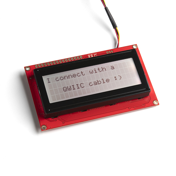
The SparkFun SerLCD is an AVR-based, serial enabled LCD that provides a simple and cost effective solution for adding a 20x4 Black on RGB Liquid Crystal Display into your project. We've seriously overhauled the PCB design on the back of the screen by including an ATmega328P that handles all of the screen control, meaning a backpack is no longer needed! This display can now communicate in three different ways: serial, I2C, and SPI. This version comes equipped with a Qwiic connector, bringing serial LCDs into the Qwiic ecosystem. This simplifies the number of wires needed and allows your project to display all kinds of text and numbers.
The on-board ATmega328P AVR microcontroller utilizes 11.0592 MHz crystal for greater communication accuracy with adjustable baud rates of 1200 through 1000000 but is default set at 9600. The firmware for this SerLCD is fully opensource and allows for any customizations you may need.
Note: Since the SerLCD is a 3.3V device, please make sure you convert to 3.3V logic depending on your chosen microcontroller or single board computer. Otherwise, you may risk damaging your board.
The SparkFun Qwiic Connect System is an ecosystem of I2C sensors, actuators, shields and cables that make prototyping faster and less prone to error. All Qwiic-enabled boards use a common 1mm pitch, 4-pin JST connector. This reduces the amount of required PCB space, and polarized connections mean you can’t hook it up wrong.
- 20x4, Black on RGB Display
- The AVR ATMega328p (with Arduino-compatible bootloader) is populated on the back of each LCD screen and handles all of the LCD control
- Three communication options: Serial, I2C and SPI
- Adjustable I2C address controlled via software special commands (0x72 default)
- Qwiic connection
- Emergency reset to factory settings (Jumper RX to GND on bootup)
- Operational backspace character
- Incoming buffer stores up to 80 characters
- Pulse width modulation of backlight allows direct control of backlight brightness and current consumption
- Pulse width modulation of contrast allows for software defined contrast amount.
- User definable splash screen
- Open-sourced firmware and Arduino-compatible bootloader enables updates via the Arduino IDE
- Input voltage: 3.3V-9V (3.3V only via Qwiic connector and "+" pin)
- I/O logic levels: 3.3V
- Current consumption @ 3.3V
- minimum with no characters
- 4.5mA (LEDs off)
- maximum with all character spaces filled
- 21.7mA (red)
- 17.2mA (green)
- 15.5mA (blue)
- 41.1mA (white)
- minimum with no characters
- Dimensions (LxWxH): 97.67mm x 60.23mm x 15.32mm
- Weight: 0.1532 oz.
SparkFun 20x4 SerLCD - RGB Backlight (Qwiic) Product Help and Resources
AVR-Based Serial Enabled LCDs Hookup Guide
August 2, 2018
The AVR-based Qwiic Serial Enabled LCDs are a simple and cost effective solution to include in your project. These screens are based on the HD44780 controller, and include ATmega328P with an Arduino compatible bootloader. They accept control commands via Serial, SPI and I2C (via PTH headers or Qwiic connector). In this tutorial, we will show examples of a simple setup and go through each communication option.
Qwiic GPS Clock
September 14, 2020
What time is it? Time for you to... Qwiic-ly build a GPS clock and output it to a display! This project provides you with the current date and time using GPS satellites. Read the date and time as a digital or analog clock. Or even configure the clock for military, your time zone, or automatically adjust the time for daylight savings time!
Qwiic Digital Desk Sign with MicroMod
June 30, 2022
Make a Qwiic-enabled digital desk sign with a MicroMod SAMD51 Processor Board's USB Host and a USB keyboard!
Qwiic SHIM Kit for Raspberry Pi Hookup Guide
February 16, 2021
Get started with the Serial LCD with RGB backlight and 9DoF IMU (ICM-20948) via I2C using the Qwiic system and Python on a Raspberry Pi! Take sensor readings and display them in the serial terminal or SerLCD.
Sending Sensor Data Over WiFi
January 16, 2022
This tutorial will show you how setup a simple peer-to-peer connection to send and receive sensor data between two ESP32 WiFi boards.
Core Skill: Programming
If a board needs code or communicates somehow, you're going to need to know how to program or interface with it. The programming skill is all about communication and code.
Skill Level: Rookie - You will need a better fundamental understand of what code is, and how it works. You will be using beginner-level software and development tools like Arduino. You will be dealing directly with code, but numerous examples and libraries are available. Sensors or shields will communicate with serial or TTL.
See all skill levels
Core Skill: Electrical Prototyping
If it requires power, you need to know how much, what all the pins do, and how to hook it up. You may need to reference datasheets, schematics, and know the ins and outs of electronics.
Skill Level: Rookie - You may be required to know a bit more about the component, such as orientation, or how to hook it up, in addition to power requirements. You will need to understand polarized components.
See all skill levels
Comments
Looking for answers to technical questions?
We welcome your comments and suggestions below. However, if you are looking for solutions to technical questions please see our Technical Assistance page.
Customer Reviews
4.6 out of 5
Based on 16 ratings:
Nice!!!
Simple set up, easy to mount, and great examples! Piece of cake!
Mixs feelings
Just what I wanted, But not working right. I get it to print what I want, then it disappears - even after reseting. I tried three differnt setups, and It does the same thing.
Qwic and easy to use,
Have only used it in I2C mode and it works very well.
Very nice!
After pip3ing the library, it works great with my RPi. The light is bright and can produce any color with RGB command. It'd be nice if it had a QWIIC socket but it can easily be mounted with the Sparkfun QWIIC adapter board (https://www.sparkfun.com/products/14495)... The legs even align with the mounting holes in the adapter.
Worked perfectly
I just needed a screen for feed back on some of the automation I was using. By using text and color I can tell the step and state of the project at all times.
Wonderful for quick projects with RedBoard QWIIC
I like these in conjunction with the RedBoard QWIIC as I can very simply plug the two together and have a display for my little applications. The IIC interface is a little slow for some applications so I buffer the data and then update the display when the program has time. Working that way I can use it to display near real-time data.
Works GREAT
Was really easy to get up and running with. Only took me a few minutes and works like a champ. Rugged, bright, and clear to see.
Works GREAT
Was really easy to get up and running with. Only took me a few minutes and works like a champ. Rugged, bright, and clear to see.
20X4 LCD
I was a little confused by the 3.3V. The qwiic connector is 3.3V from the 5V redboard, but I was having trouble getting it to work so I changed the redboard to 3.3V and it worked but I don't know why. Also, even though the display can display 80 characters, if I write lcd.print () anything longer that 32 characters gets truncated so I have to break it up into multiple lcd.print() of 32 characters or less. Most of the problems are normal learning curve stuff. By the way, I love your stuff and would buy more but a lot of it isn't in stock.
Excellent design
Fantastic LCD screen that works great with the Qwiic connectors as well as the breakout pins for I2C (have not tried SPI or serial). We use it in all our 3.3V projects now.
One small thing that is not ideal and would make this even better: the 4 mounting holes in the corner are too small and don't fit M3 or 4-40 machine screws (all other LCD screens with this footprint that are on the market have slightly bigger mounting holes that fit both of those screw types). Maybe something that can be fixed in the next version?
A great option for a bigger character LCD
I bought this screen to replace a 16x2 SerLCD I was using in a project. So far it has been just what I wanted, and it's very easy to get working out of the box.
I've only had one real issue, which is that the LCD seems to consistently drop characters when receiving a full (80 char) buffer at 115.2k baud. I was able to work around this issue by sending my screen buffer line by line with a small delay in between, so no big deal. I also presumably could have switched to the I2C or SPI interfaces.
Overall I am very happy with this product and it works as expected.
Does what it says on the tin!
Bought this for a robot remote control I'm building. Worked great out of the box.
Literally plugged it in, downloaded the SerLCD library into the Arduino IDE, and ran a couple of example sketches.
No problems, no fuss, no strange behaviours nor need for random capacitors...
When I ordered it, I neglected to notice the RGB backlight (was more interested in the 20x4 screen) so that was a nice bonus.
Trying to get to work with RP2040 Pro Micro
This display is working very nicely on my Pi400 using one of the examples. However, I also want it to work with an RP2040 Pro Micro, also with Thonny. Trying the "Hello World" example I get "ImportError: no module named 'future' from line 1 which is "from future import print_function". I imported "sparkfun_qwiic_serlcd", but there must be something I missed.
Add the future package https://blog.finxter.com/fixed-modulenotfounderror-no-module-named-future/ and/or install micropython on the Pi400 too :)
Qwiic LCD Really Is Quick
I did have a good experience with the 20x4 LCD display. Connection just couldn't be easier with the simple qwiic cable. I did have a little trouble finding the right drives for it because this display doesn't use the same controller as some other displays used with Arduino. But once I realized the difference, the display worked fine. I tried out all of the sample programs and all of them were functional. I recommend this device highly if you need a display on your SparkFun CPU.
Extremely easy to use
My original project had a 16x2 GPIO based display but I was running out of GPIOs so I decided to redesign my project to use the I2C display shown here. I was very happy I did because now I have all of those extra GPIOs that I can use. The Sparkfun library that targeted this display was also very easy to use.
perfect for multiple sensor data display
With one Leonardo, a level shifter, and this display I'm able to simultaneously display 7 temperature readings, 3 flow rate readings, and a COP calculation. Although I did have to add an SN74HC151 MUX since the Leonardo has only one T1 port (pin 12) to the Timer/Counters for the three frequency measurements. But this display is very easy to use and much less costly than eleven 4-digit 7-segment LED displays.

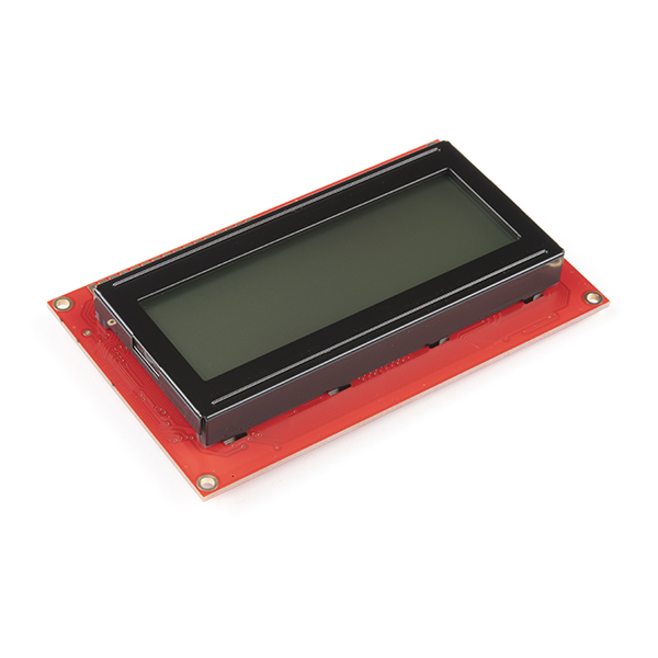
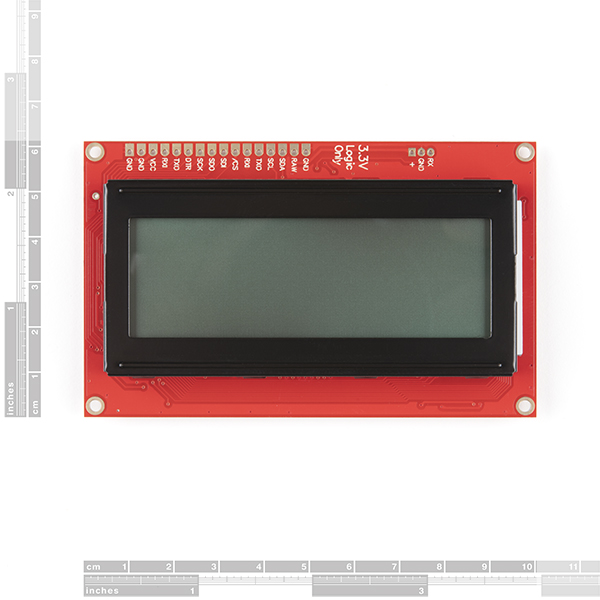
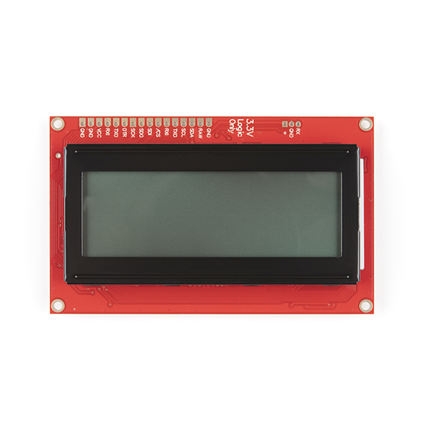
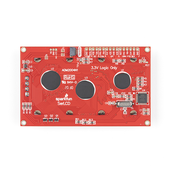
What is the actual viewing area of the display? I'm trying to find a bezel and the dimensional drawing does not indicate this.
-- HELP: Long Strings Truncating At 30-characters --
I have a student group who is attempting to integrate this LCD into their project. It's almost certainly an issue with the code, but they are experiencing a truncation of strings that are printed to the screen, specifically when strings are longer than 30 characters.
For context, they are using the Qwic connection, using the Wire library to communicate with the screen via I2C. The long strings are successfully wrapped from the first 20-character-long line down to the second line, but as I said, strings are consistently truncated to 30 characters (cutting off in the middle of the second row)...
As for the code, we've simply tried using the example code found here, then modifying the sample string to be longer...
This displays the following on the 20x4 display: