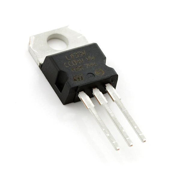
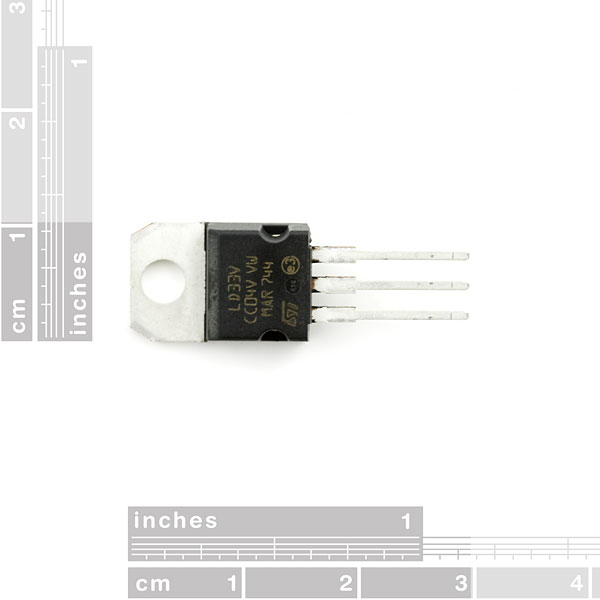
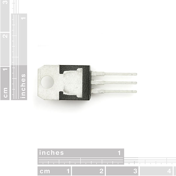
This is the basic LD1117V33 voltage regulator, a low drop positive regulator with a 3.3V fixed output voltage. This fixed regulator provides a great amount of stability and protection for your project and with its on chip trimming this regulator is able to reach an output voltage tolerance within ±1%. Each one of these voltage regulators can output a max current of 800mA.
- Output Voltage: 3.3V
- Output Current: 800mA
- Dropout Voltage: 1V
- Internal Current and Thermal Limit
Voltage Regulator - 3.3V Product Help and Resources
RedStick Hookup Guide
January 28, 2016
Learn about the SparkFun RedStick, a USB thumb drive-sized Arduino-compatible development platform.
Beginner Parts Kit Identification Guide
March 22, 2019
The essential parts for beginning (or even experienced) hobbyists that gives you all of the basic through-hole components you will need to get started playing with embedded projects. We'll identify a few parts in the kit and provide a few basic circuits to get started!
Core Skill: Soldering
This skill defines how difficult the soldering is on a particular product. It might be a couple simple solder joints, or require special reflow tools.
Skill Level: Noob - Some basic soldering is required, but it is limited to a just a few pins, basic through-hole soldering, and couple (if any) polarized components. A basic soldering iron is all you should need.
See all skill levels
Core Skill: Electrical Prototyping
If it requires power, you need to know how much, what all the pins do, and how to hook it up. You may need to reference datasheets, schematics, and know the ins and outs of electronics.
Skill Level: Competent - You will be required to reference a datasheet or schematic to know how to use a component. Your knowledge of a datasheet will only require basic features like power requirements, pinouts, or communications type. Also, you may need a power supply that?s greater than 12V or more than 1A worth of current.
See all skill levels
Comments
Looking for answers to technical questions?
We welcome your comments and suggestions below. However, if you are looking for solutions to technical questions please see our Technical Assistance page.
Customer Reviews
5 out of 5
Based on 3 ratings:
3 of 3 found this helpful:
Voltage, regulated
This turned my 5v into 3.3v! As expected, of course.
2 of 2 found this helpful:
Stable and useful
Here is an easy to use constant 3.3 volts It's useful to power a newer CPU board and a herd of sensors. Except for a pin swap, it is as easy to use as the 7805. Recommended.


How much heat can this dissipate? 2w?
Today I learn a valuable lesson. Buy the parts first, then order the boards.
Today I learn a valuable lesson. Do NOT assume all TO-220 voltage regulators have same pin-out. Check datasheet before soldering!
May I ask where you found the data sheet? The one here seems to be damaged.
Kinda sneaky how these got changed around. Luckily I was only breadboarding.
The 7833s go: IGO: Input Ground Output
The LD33Vs go: GOI: Ground Output Input
These pinouts are all left to right as seen in the first image above. The tabs of both types are connected to the center pins.
RTFM :)
And I too have now lost parts due to this pinout. Was getting really close to getting that xBee working too before I cooked it. The pinout on the one I got is correct as far as the datasheet is concerned and I had it working once. Then rebuilt the power supply on the breadboard from my memory of the 5v one which is totally different. PLEASE NOTE: this pinout is not the same as the millions of other regulators you’ve used.
Another suggestion--sell these two ICs under different product numbers since they have different pin configurations. That way you'll know what you're getting.
I'm a huge fan of Sparkfun, but I got burned pretty bad on this one--I ended up losing a custom PCB and most of the parts on it. Shame on me for not double checking the number on the IC but I never thought in a million years I'd get the same part with a different configuration...
one more. the 78xx was created in the dark ages. and has nothing at all to do with the above part. It was invented by Robert C. Dobkin and Robert J. Widlar in 1970[1] while they worked at National Semiconductor. 43 years ago, my hay day. the above is 2004 creation, the original engineers are dead or retired. now. RIP if latter. dont feel bad, i burned my hand on a 78xx , in 1970, wired wrong, there is no protection diode on the 78. sorry. that same protection diode above, blows up your 3v parts, with supply minus 0.7v (protects reg, but not load , sorry) boom.
one other warning, the tab and back side. are connected to the ground tab i think?, so be careful where it touches. notice they forgot to say. on bipolar transistors its usually the Collector, the packaging engineer said "the frame photos dont have pins ID'd because, "we put different die, in this package" so its a pure package drawing only. That is the excuse and a contradiction, in semi business.. I thank LD is STI only prefix. best post, RTM. sure.. but better, is RTMFM, (the F is formulated), as in coded......
OMG, you're T.S.!!
yes, page 2 is clear,, if you know conventions. even old NS and Fairchild in 70s did this... but most makers do poor spec pages, IMO, 50 years now. the good ones, use quasi 3d views. isometric so you can clearly see what side is in view. but the PDF above is TOP view , plastic side. like above photo view 1, see that, 3D effect too bad you dont put a 1 on the left there....helping others to read Data sheets. same with the mech. drawing, missing the pin numbers, strike 2. i asked our marketing, why this is done, (I worked at Phillips semi) answer. to make it look like or competitors. they were ghastly afraid of looking different. (pure fear) reason being, so as not to scare away costumers. so, its a tradition , this method, of poor pinout view. I can tell you there are worse drawings, what i do,if even slightly not sure, i power it up , by self and check it. take 1min with a bench variable supply or if poor, a 9vdc transistor battery (smoke alarm bat).. You could loose it all, its only the regulator .. LOL
guys make sure you triple check the pins on this thing, i don't mean to be a troll, but this thing somehow killed my netduino mini. So make sure you put it on a bread board and test it, before you hook it up to something else... and sparkfun whats up with the laziness? just make a clear note on the product description. this really upset me.
So you have one and probably tested it by now?
Or at least you know which pinout is wrong?
Could you share it with us?
take a look at dent's comment. he has the correct pins i tihnk. still make sure you test it with a battery or something before you hook it up to your actual project or whatever.
WTF? You are selling two completely different parts with DIFFERENT pinouts as the SAME NUMBER????
WTF?
And this is going to help your customers how, exactly???
What?
One of the possible parts is low-dropout and the other is not. Any way to predict which part you'll get if you order?
Not sure if someone had this happen to them but when I plug in a LiPo battery charged to 4.5V it outputs 3.7V and gets really hot. And when trying a 9V battery (to see if the reason the output was 3.7 instead of 3.3V due to a lower input voltage) I ended up with 7.24V and it got REALLY hot really quickly (to no surprise). Anyone have similar issues?
A dropout voltage of 1V is nothing to brag about. I've seen LDOs with dropout voltages as low as 50mV.
Anyone know if this chip is good for converting a 0-5V input into a 0-3V output?
These are usually used for converting a higher voltage power supply to what your chip needs as an input. In this case, it will take any input voltage in the range 4.75V to 15V and output a consistent 3.3V. If you're talking about digital logic levels (e.g. a 5V digital signal output to a 3.3V device's input pin, then no; you'd want this part for that: https://www.sparkfun.com/products/12009
Can anyone confirm the pinout on this? Datasheet says 1: GND 2: Vout 3: Vin - the Eagle footprint however is 1: Vin 2: GND 3: Vout
Would this work for powering 3.3V devices from one of the 3.7V LiPo batteries you sell? Reading the datasheet I noticed the dropout voltage is 1 volt with a 100mA load, which is very close to what I think my circuit will draw. Because of this the minimum voltage I can use as input is 4.3 volts, a.k.a. I'm f*cked. And the reason why I'll use a LiPo is that I need the device to be as small and thin as possible.
I'm planning the layout of a project including this component on perfboard, so would this normally be standing on a finished board or should I lay it down?
You can use it either way. Just keep in mind if you're going to bend the legs to lay it flat on the board, you need to be careful not to break the legs off. I personally adjust these for height clearance after I've soldered them into prototyping areas in my own projects. Also, keep in mind having it stand up will allow for it to get a bit more air flow-these do tend to run warm.
the TO-220 CASE moniker is lacking. the TO-220 is a base family of parts and has many version. and is a JEDEC standard , since even my younger days in 1970s. the codes vary MAKER TOO. never assume one co. uses same package codes. ever. and WIN. this applies to transistors in spades. too. look up TO92 and see 3 forms. so when buying parts, get the data sheet and see what suffix your brand uses, for the TO-220. case.
and yes, spark fun fogot to say which case it is, I suspect they forgot or just dont know cases too well. now go to mouser, a real distributor. and see how the sell parts. at 55 cents each qty 1. the photo shows STI maker. and they only make 1 , 220 type. the STI data sheet shows. facing plastic 1 gnd, 2 out, 3 in , left to right leads towards you. is yours STI? you never said.
Could someone please fix the Eagle library pins for this 3.3V regulator?!?
hello srry for this nooby question but um im gonna try to run a string of leds running 2.0v-3.3v off a 9v battery how should i hook this up
First, check the datasheet to learn the pinout of this part. (There are several different packages in the datasheet, this one is in the TO-220 package.)
Next, connect your +9V to VIN, and your battery ground to GND.
Now, 3.3V will be coming out of the VOUT pin. (The GND is shared between the input and output.)
You'll probably need at least one resistor between the 3.3V output and your LEDs. There are a bunch of good online calculators for this, such as this one for single LEDs, and this one for multiple LEDs. They will ask for the LEDs forward voltage and current, you can find this in the datasheet for your LEDs. Have fun!
thank you this will help very much thanks
Is 15v the absolute maximum Voltage? Can't seem to find absolute max in the datasheet.
pg 3 of the DS, table 2 - "Table 2: Absolute Maximum Ratings" - Vin=15V....?
I'm really new to this so I'm sorry if this is a newbish question, but do I basically just plug one pin into my 6V input, one pin into ground and the last will put out a nice 3.3V? Thanks!
For many applications, this one is unnecessaraly big. How about storing something like MCP1702-33?
I ordered several of these a while back. I can confirm that the ones I received match the data sheet. (From left to right facing the plastic-ish side) 1: GND 2: Vout 3: Vin
Guys: pinouts for voltage regulators are usually: 1: in; 2: GND; 3: out; and the gnd for the big back part as well
Which is the correct pinout?
The datasheet says:
1: GND
2: Vout
3: Vin
While both the LM7805 which is also a TO-220 package
and the Eagle library of April 13th 2010 (V_REG_LD1117X) have:
1: Vin
2: GND
3: Vout
Gintaras:<br />
<br />
Suggestion; sell surface mount versions of these, I have a hard time finding them in other stores.
Something like this?
http://www.sparkfun.com/commerce/product_info.php?products_id=595
No, the 3.3 and 5 volts ones.
We'll definitely look into it!
Just incase anyone else was confused by the doc sheet on this.
it is ground, V out, V in.
The PDF made me think it was V in, Ground, V out