SparkFun SIM Card Socket Breakout
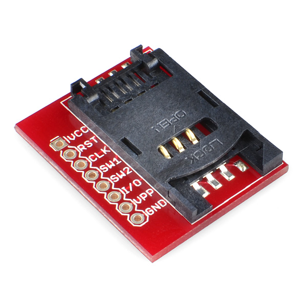
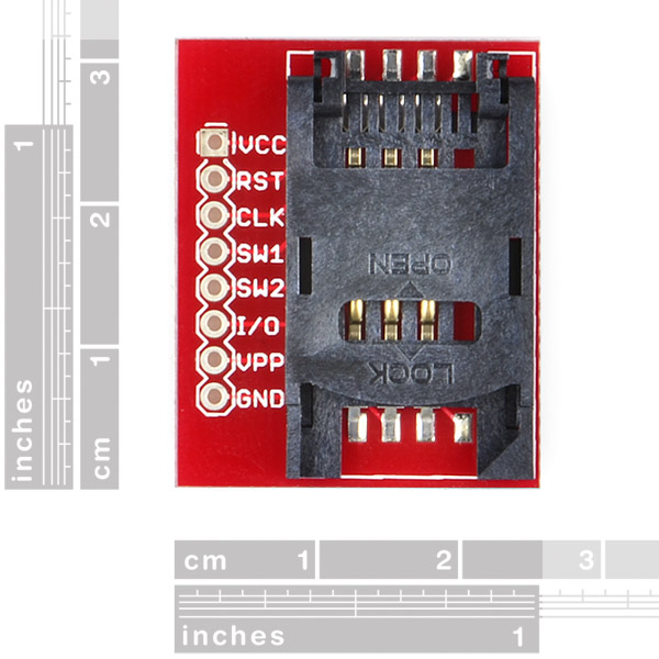
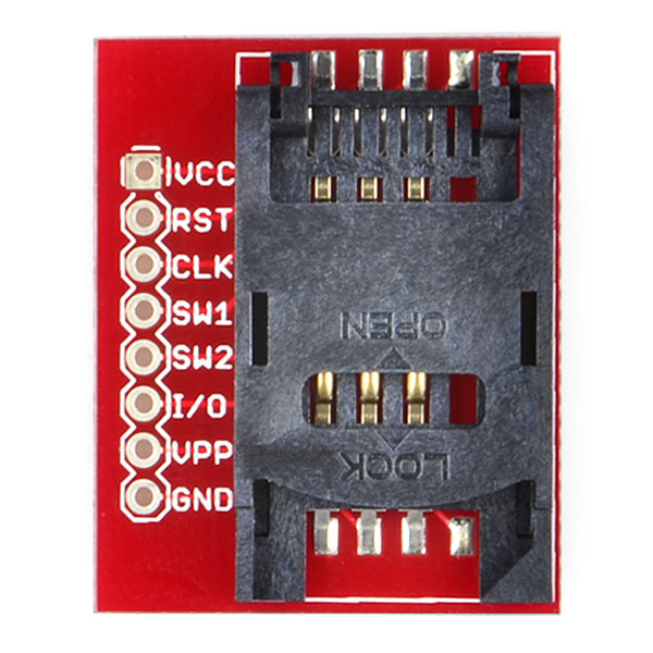
This is a full 8-pin breakout for the SIM socket allowing direct access to SIM communication.
Note: This breakout board was originally designed for a SIM socket with a switch for card detection. We have since switched to a socket that does not have this feature so the SW1 and SW2 pins have nothing to break out and can be considered NC. The 6 SIM card pins, however, are still broken out correctly.
- Schematic
- Eagle Files
- GitHub (Design Files)
SparkFun SIM Card Socket Breakout Product Help and Resources
Core Skill: Soldering
This skill defines how difficult the soldering is on a particular product. It might be a couple simple solder joints, or require special reflow tools.
Skill Level: Noob - Some basic soldering is required, but it is limited to a just a few pins, basic through-hole soldering, and couple (if any) polarized components. A basic soldering iron is all you should need.
See all skill levels
Comments
Looking for answers to technical questions?
We welcome your comments and suggestions below. However, if you are looking for solutions to technical questions please see our Technical Assistance page.
Customer Reviews
No reviews yet.


The SIM sockets you sell are 6 pin, but the board picture here is 8 pin and apparently not the same model (despite saying 6-pin in the description)? Are you using different SIM sockets for these two products?
admitting this is a very overdue reply, the 8 pin breakout board includes 2 switches added by sparkfun, which can be used to "detect" when or if a sim card has been inserted, telling your micro-controller to begin sim card communications.
Hi! Can I get eagle footprint of this breakout like in other breakout boards?
Very good morning to all of you I have the following question: Where is connected SW1 and SW2 pins in my GSM / GPRS SM5100B-D model?
Thank you for your service.It is excellent!
And I have another question. I bought the GSM / GPRS Module SM5100B-D model. Notice in the Datasheet that a connection whose name SIM_DET. SIM_DET connector must be connected to SW1?
Sparkfun Hello, I would like to know what are the dimensions of the SIM Card. And that distance is between Pad's. I'd be very grateful for this information.
Anyone know where to find a SIM Card Breakout. The difference being it's a little simcard with wire extension. I want to use the board here at sparkfun to create a sim card extension cable. I haven't had much success finding one.
Does anyone know of information on talking a SIM card and using the network? I am using it in a project to remotely control my device via text messages such as a text with 1:ON means turn on my output 1 and I would get a message back that message was received and output is on. There are actual devices for this from Automation MFR's like wago.us but I want to make my own. :)
There are a bunch of commands for talking with SIM cards, but as for using a cellular network, you're going to need more than just a card to get it working. SIM cards have a bunch of authentication mechanisms, including computation of encryption keys (one command, called "Get Challenge" involves calculating security codes from a 64-bit number) and also communication to and from the local cell towers.
You're better off using a dedicated cellular board, or picking up an old cell phone that has a SIM socket and isn't SIM-locked to its original carrier. Many Nokia phones have a serial port (called F-bus) and there are (some) articles on commands that can be used to send and receive text messages.
I need to know if it includes a SIM socket. Cmon sparkfun, please improve your descriptions. They are lacking.
If it didn't include the SIM socket, we'd be very clear about that. But it does, just as all the above pictures indicate.
When is a Micro Sim Version of this coming out? or a Micro SIM breakout board in general would be nice =)
I noticed the breakout for this has SW1/SW2, how have you mechanically achieved this? I'm putting this part on my board without the breakout and would like to be able to tell when a SIM is plugged in. A schematic for the breakout would be great.