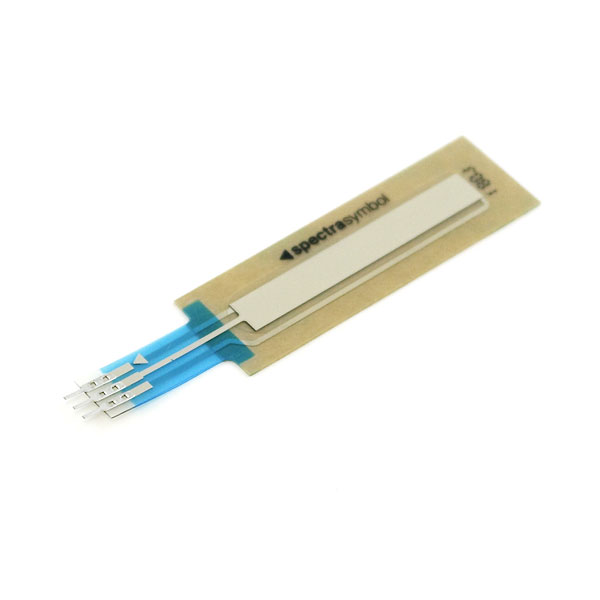
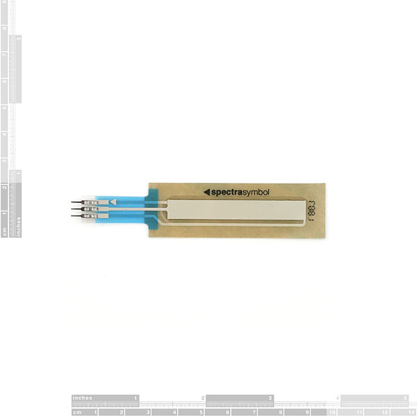
These are very thin variable potentiometers. By pressing down on various parts of the strip, the resistance linearly changes from 100Ohms to 10,000Ohms allowing the user to very accurately calculate the relative position on the strip. Can be used as an accurate positional indicator for CNC head positioning, variable user input (volume level input for example), straight user input (multiple button areas translate to given resistance levels), and many other applications.
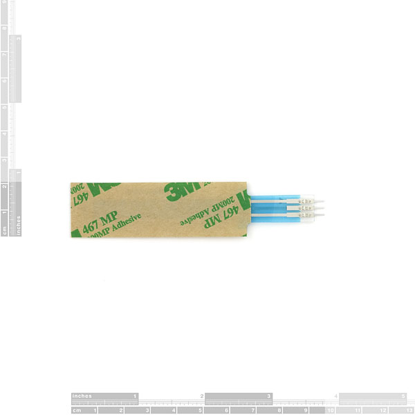
Unit comes with adhesive backing. Connector is 0.1" spaced and bread board friendly.
Note: These potentiometers work great with a finger, or stylus.
SoftPot Membrane Potentiometer - 50mm Product Help and Resources
Hackers in Residence - The ElectricBone
June 25, 2014
Drum machines and keyboards have been the standard for making digital music, but how do you make electronic music if you're trained to play the trombone? One of our Hackers in Residence, Carlos Mello, took it upon himself to find a solution to that very question.
SIK Keyboard Instrument
April 15, 2016
We can use the parts and concepts in the SparkFun Invetor's Kit to make a primitive keyboard instrument.
SoftPot Hookup Guide
May 5, 2016
Equip your Arduino project with a sliding soft potentiometer to monitor position or adding linear control to your project.
Core Skill: Electrical Prototyping
If it requires power, you need to know how much, what all the pins do, and how to hook it up. You may need to reference datasheets, schematics, and know the ins and outs of electronics.
Skill Level: Noob - You don't need to reference a datasheet, but you will need to know basic power requirements.
See all skill levels
Comments
Looking for answers to technical questions?
We welcome your comments and suggestions below. However, if you are looking for solutions to technical questions please see our Technical Assistance page.
Customer Reviews
5 out of 5
Based on 3 ratings:
2 of 3 found this helpful:
Still going through my degree and...
Discovering all these neat products that we don't get to play with in school. I intend to incorporate this under the chin (and running the length of the sock) of one of my wife's dragons (embedded in the sculpey) in hopes of varying the current going to the mused wire embedded in the wings, therefore making them twitch when you scratch the sculpture. Unfortunately school does take most of my time... stay tuned?
So many awesome uses
This thing is so cool. Its more accurate than I imagined. I used it for a ribbon for many types of synth projects and its awesome in every application.
Softpot membrane pot
It works fine especially with the FCI Clincher connectors (COM-14196). You should also offer the longer versions of the pot.


I got one of these in an Arduino inventors kit. One of the projects uses it (as a voltage divider, reading the output from the middle pin) to control the color of an RGB LED. The sensor was not acting at all the way I thought it would when I was not touching it. I realized that when nothing is touching the sensor, the voltage is at about 33% of the voltage range. Touch the sensor near the connections, and the voltage drops to nearly 0 or ground. Touch it near the top (away from the connections) and the output voltage rises to whatever the high pin is. This makes it impossible to tell when the sensor is being touched and when it is not. I put a resister (10K) between the ground pin and the output pin, and now the output is exactly what I want. I can look for a voltage of 0 to see that it is not being touched, any value above zero means it is being pressed. The higher the voltage, the higher on the strip it is being pressed.
This is great advice. I had the same experience. Put a 10k between ground and output and you'll get a useable reading.
Tony's "..put a resister (10K) between the ground pin and the output pin, and...any value above zero means it is being pressed. The higher the voltage, the higher on the strip it is being pressed." should be added to the description.
I didn't find the way to get 0 value when the sensor is not pressed until I read your post, which is the therorical reason of putting the resistor?
A suggestion for sparkfun team: This tip should be in the guide of the inventor's kit, for the beginners is essential
The simplest way to think about it is you are "pulling" the output to ground, or 0 volts, so that will be the default reading. You use a large resister so that the effect is not very strong and can easily be overridden by the rest of the circuit. Also, using a large resister limits the amount of current being drawn / power being wasted.
Thanks Tony, that resister totally solved the problems I was having with my SoftPot, and as it happens, also a Sharp IR range finder!
EDIT: Damnit, fancy formatting failed.
for getting rid of noise - connect a capacitor between the input pin and groun. I used a 1uf which works perfectly. pretty insane to me that sparkfun doesn't mention the necessity of the pullup/pulldown resistor... this company has a great stock, but all of their information seems to be lacking depth and has caused me a lot of issues in the past.
This softpot came in the SparkFun Inventor's Kit. The pins do not fit into the breadboard as shown in the kit guide. I didn't want to ruin my new softpot by modifying the pins (and I'm too much of a newbie to solder yet). So, I solved the problem by gently pulling the black heat shrink plastic off one end of three jumper wires. (I only ruined one wire, before successfully having 3 wires with a black end removed and the pin exposed). I then attached the 3 plastic bits to the three prongs on the softpot. Lastly, I gently inserted the now exposed pins of my jumper wires into the 3 plastic bits until the ends just ever so slightly appeared at the base of the softpot. This created a fairly stable connection between the three jumper wires and the softpot and I was able to complete the circuit successfully.
Why we need to put resistor between Ground and output pin. Sorry my question may be very silly but I am new to electronics...
i Love Analog Sensors ;)
Hi gyus, I'd like to use this in my project where I'd like to measure distance traveled by a moving stage. The thing is the stage only moves from about 2-5mm, you think this sensor can resolve changes this small? The sensor would be mounted on a flat hard (aluminum) surface and the stage would be "touching" the sensor using the supplied "stylus" so the force applied will be quite constant. Thanks for your tips!
.
Hi can you bend softpot membrane potentiometer along with your finger? If it can be bend then will the resistor value changes accordingly?
I made the following Python script you can run on the Beaglebone to reduce the crazy noise and output a better value range to work with, Script URL: http://pastebin.com/hfekCBuW
I found out using this script that when nothing is being pressed on the soft pot anymore it resets to the highest value. Hope you guys like this!
This component is very sensible and fragile but under right circomstances it is extremely precise. If you want an accurate reading, you have to stick it to a hard surface. When you're not touching it, it returns a lot of random values (noise), making it pretty unreliable for creating a "touch" human interface.
if they can be extremely precise, that sounds better for my purpose than using flex sensors. what about if you were wearing it on a glove and used the parameters to control effects? when you say random values whilst not touching it, how much noise/signal are you talking about please?
I noticed that too. Looks like it should work as long as you leave a little of the transparent part intact.
Seems a bit wide for what i'd like to use it for... Can it be trimmed a little bit and still operate correctly?
It can't be trimmed.
Comments on the 500mm version suggest it can.