SparkFun Ambient Light Sensor Breakout - TEMT6000
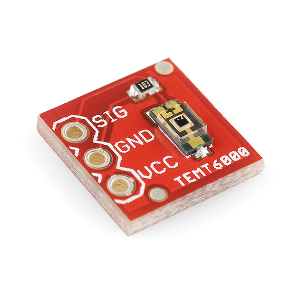
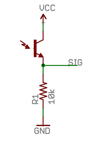
Basic breakout board for the TEMT6000 Ambient Light Sensor. Only what you need, nothing you don't. Sensor acts like a transistor - the greater the incoming light, the higher the analog voltage on the signal pin.
SparkFun Ambient Light Sensor Breakout - TEMT6000 Product Help and Resources
EL Wire Light-Up Dog Harness
October 30, 2015
Learn how to create a light-up dog harness using EL wire for when you need to take your four-legged friend for a walk in the dark.
TEMT6000 Ambient Light Sensor Hookup Guide
October 26, 2016
Bring the ability to detect light levels to any project with the SparkFun TEMT6000 Ambient Light Sensor Breakout.
Core Skill: Soldering
This skill defines how difficult the soldering is on a particular product. It might be a couple simple solder joints, or require special reflow tools.
Skill Level: Noob - Some basic soldering is required, but it is limited to a just a few pins, basic through-hole soldering, and couple (if any) polarized components. A basic soldering iron is all you should need.
See all skill levels
Core Skill: Programming
If a board needs code or communicates somehow, you're going to need to know how to program or interface with it. The programming skill is all about communication and code.
Skill Level: Rookie - You will need a better fundamental understand of what code is, and how it works. You will be using beginner-level software and development tools like Arduino. You will be dealing directly with code, but numerous examples and libraries are available. Sensors or shields will communicate with serial or TTL.
See all skill levels
Core Skill: Electrical Prototyping
If it requires power, you need to know how much, what all the pins do, and how to hook it up. You may need to reference datasheets, schematics, and know the ins and outs of electronics.
Skill Level: Noob - You don't need to reference a datasheet, but you will need to know basic power requirements.
See all skill levels
Comments
Looking for answers to technical questions?
We welcome your comments and suggestions below. However, if you are looking for solutions to technical questions please see our Technical Assistance page.
Customer Reviews
4.4 out of 5
Based on 8 ratings:
Works as Expected
Good board and clear hookup instructions. Worked great for my project!
Always order from Spark Fun. Very Quick
I got the items in less than 4 business days. very fast shipping and the item worked perfectly.
Fine
Does exactly what it is supposed to do.
Ambient Light Sensor
Works as advertised. Was simple to incorporate into Aduino project. In bright sunlight max reading is 1011 of 1023, 0 in darkness, as expected.
Great product
Works as advertised. I just wish it had some mounting holes to better attach to projects.
Great product
Works as advertised. I just wish it had some mounting holes to better attach to projects.
Great product
Works as advertised. I just wish it had some mounting holes to better attach to projects.

I had a question about the output this sensor gives off... I'm using it with a basic stamp 2pe microcontroller and haven't been sure how to convert the analog output into lux. Is there a specific equation I have to use for this or are there several (like ones that include temperature, etc)?
Although the datasheet does not provide this information, an email to Vishay got some dynamic response data. The upshot is that for the fastest response to changing light conditions one must have a high current flowing through the device. Icmax is defined at 20ma. With the 10K resistor (assuming no current out the signal line), and a 5 volt supply, than the maximum collector current is 5/10K or a tiny 500 micro amps. At this condition, rise and fall times are around 15 micro seconds. Increase Ic (by lowering the value of the resistor) and you can drop the times to bellow 10 usec.
Suggestion: Why not use the regular G/V/S layout for pinout? Gnd / Vcc / Signal? Then it'd match practically any servo connector wire pinout.
Yes, I'm using it at 3.3v. Just keep in mind, the current out of this thing is small; I'm buffering it using an op-amp.
I am using 5v with an arduino mega and this unit really impresses me. Note that this sensor reports close to 0v even when in moderate light, and you must use a bright light to get 5v out.
UPDATE: This sensor also has a very large light receiving area as even lights pointed at it from the side trigger high readings. Still happy with it!
SFE, how about a breakout board with this sensor and a logarithmic amplifier? I don't care for the difference between 100 lux and 105 lux, which you won't notice anyway, but I do care about the difference between 10 lux, 100 lux and 1000 lux. Log amp, please!
The ISL76671 is a newer, more sensitive analog light sensor, for very low light levels. Please make a breakout board for it! :)
why use this instead of a photoresistor?
With a photoresistor you build a voltage divider which is anything but linear, this one is linear. Also, a phototransistor has a much wider range and is faster. Phototransistors are being used to trigger slave strobe light in photostudios, a photoresistor is orders of magnitude too slow for this.
Yeah, I'm kinda wondering the same thing.
datasheet 404'd:( I found it here
What is the range of possible values that this will return? 0 - 1023?
Thanks
why 10k resistor? how to calculate this?
Would i have to buy the sensor itself? or does it come with the breakout board?
It comes on the board.
Does This come with the sensor itself? or do i have to buy it seperatly? THX
Yes, the sensor is in place on the pcb.
U can use digitall read with it
Technically yes (you will get HIGH and LOW for certain amounts of light), but I suggest that you use analog to get an exact value.
Would this be a good device for measuring and data logging sunlight in a garden? Also, is there a waterproof version, or a good way to waterproof this without diffusing the light from hitting the sensor? Thanks!
Would anyone happen to know the bandwidth for this summabitch? I haven't been able to find it anywhere, including Vishay's website.
The data sheet shows an input capacitance (C) of 16 pF. The breakout schematic shows a 10K resistance (R) in series. R*C = 160 nS; the RC time constant. Lets call it 200 so that 5 time constants is 1 microsecond. So my, rough guess, expectation is that you should be able to get at least 500 kHz "bandwidth". My guess is that it would handle any "fast" Arduino project, for example a lightning flash sensor. Another post (Skye) indicates a 15 usec response. Still fast enough for most general light sensing. I think its time for me to get one and test it!
Exhibits wonderful non-linearity in the output... Go code yourself a correction algorithm...
Amazingly simple to use.
I'm using it as a trigger in a spectrometer, gives the go signal when the emission starts.
highly stable and incredibly easy to work with. Only problem is, my fingers are too big
Remarkable. I swapped this in place of a potentiometer in my Arduino project and it worked exactly as expected without any changes. It's great to have this as a breakout.
Now I have to modify the software to provide some dampening.
I'm using it at 3.3v (with a "mbed - LPC1768 Development Board" bought on Sparkfun as well). Just works.
I would like to use this in an application where I need much higher resolution, but it won't need to measure more than 2 lux or so. If I just put a big resistor on the ground pin, will that effectively multiply the voltage on the signal pin? Also, while this won't need to actively measure more than 2 lux, it will still regularly be exposed to 100+ lux while it's on. If putting the resistor on there will fry a 5V picaxe I/O pin, it won't work.
If this doesn't work, I'd appreciate any ideas for something that would. I would just use a CdS photoresistor, but linearity is very helpful.
What are you doing with it that requires significant current? I was going to sample it with a high-impedance ADC input. I'm assuming I don't need to buffer that, right?)
Anyone know if this will work at 3.3V?
Yes, but you should then set your analog voltage reference to 3.3v for a more representative result.
Yes it will. The series resistor determines the output voltage. If there's so much light that the output would want to go higher than 3.3V, decrease the resistor value.