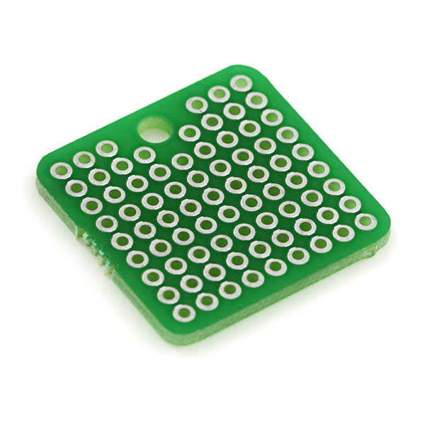
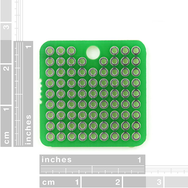
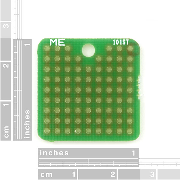
This is a very simple but extremely handy, 1" square, single sided perf board. Standard 0.1" spacing with a 4-40 (3mm) hole for mounting. Every three holes are connected with a 20mil trace.
** Package of 2**
ProtoBoard - Square 1" Single Sided Product Help and Resources
Core Skill: Soldering
This skill defines how difficult the soldering is on a particular product. It might be a couple simple solder joints, or require special reflow tools.
Skill Level: Noob - Some basic soldering is required, but it is limited to a just a few pins, basic through-hole soldering, and couple (if any) polarized components. A basic soldering iron is all you should need.
See all skill levels
Comments
Looking for answers to technical questions?
We welcome your comments and suggestions below. However, if you are looking for solutions to technical questions please see our Technical Assistance page.
Customer Reviews
3.8 out of 5
Based on 4 ratings:
3 of 3 found this helpful:
Great for tiny projects
I love these things. As with most prototyping boards, the conductive ring pads (I'm not sure what they're called) will come off if they're overheated.
If you're having a hard time seeing the traces, try putting the board in front of a flashlight or a lamp or something.
1 of 1 found this helpful:
Great price! where's the spec sheet?
These are a great size and a great value. Came in handy for my current project building IR tachometers. I was a little surprised that they didn't come with a spec sheet though as just about every other Sparkfun product has one.
1 of 2 found this helpful:
needs at least some traces
I bought a slew of these for a large project full of small elements. The price and size are great as is the mounting hole but I am finding them very difficult to use because the traces described are only visible with a magnifying glass and they don't seem to connect the 3 holes. Consequently I am having to bridge all connections which is slow and messy. Maybe mine are dysfunctional? Also 2 power rails that run all the way through would make this product more useful to me.
Hi, Sorry for the troubles. The connections should be there. We do sell a different protoboard that is not internally connected. If you do not have any internal traces, we may have made a mistake and sent you the wrong thing. If you have some internal traces, try setting the board so that the mounting hole is pointed up and away from you(like the second product picture), then the traces will go up and down and be connected 3 rows at a time.
Devil in the details.....
I purchased these to create little 555 timer demo projects to hand out to potential employers to show my soldering skills, component selection, circuit design etc. I have admittedly failed in the product selection by not fully reading the description.
Admittedly I just looked at the 1" square single sided board title and said perfect, so I ordered up a few sets. It took burning through 2 sets of components and being completely baffled as to why my circuit wasn't working as designed, despite working flawlessly on the breadboard. I eventually fried both 555 timers during testing.
After going back and reading the description in more detail it does in fact state that every three holes is connected by a trace. Now looking at the board you would not see that. If you're going to have 3 traces connected you need to make that clear by traces connecting the holes on the surface.
Not very productive as a universal proto board if the traces are interconnected and not clearly marked with interconnected traces. This product could easily be updated to show the interconnected traces clearly. Would also be great if you could make a similar model with all non-interconnected traces and double sided.
I only lost 2 555 timers, 6 resistors, 4 capacitors, 2 led's, 2 ptc's, 2 zeners, a few hours of my time and a couple handfuls of hair!
Its all good though, chalk it up to learning and reading the specs and product description no matter how simple the device or product may seem to be.
Thanks, the hair should grow back! ;)


What is the thickness of these boards?
The same thickness as most of our (PCB) boards, about as thick as a quarter or around 2 mm.
I don't understand "Every three holes are connected with a 20mil trace". from looking at the back of the board it looks every hole in a column is connected. can somebody explain that?
Same question ! ? up ;)
It's every 3... and 2x2 and 1x4. The back of the board isn't really a good indicator, as you're just looking at the top traces through the board material, which blurs things out; though if you look closely, you can still tell that between every group of 3 rows, the apparent traces do appear slightly lighter.
The top of the board is a better indicator, as the solder stop/mask around the pads shows a slight 'bump' where the traces are. From that, you can see that it does connect pads in groups of 3 - except around the mounting hole; at its sides it's groups of 2, and right below it is 1 group of 4.
Image for clarification: imgur.com/EPo5h0T
Seriosly, this product is four years old, this image should be part of the product description! Thanks a lot for providing it.
I wish you guys would've made it just a little bigger (10x10) so I could fit a picaxe 20x on it. Still, I'm buying some of these
Little warning that the hole right below ('below' as in the 2nd picture) the mounting hole is connected to the three holes under it.
Okay, excuse my ignorance, but I could build circuits for this on my breadboard, and then (accounting for the rows of three) build them permanently on this when they're working properly?
You should carry these same size but in SMD that I'd buy tons of!
You could cut a ProtoBoard - Bandicoot (SMD) into multiple squares ;)
I just ordered 13 of these boards. Any idea how thin is the board used in this?