SparkFun Thumb Joystick Breakout
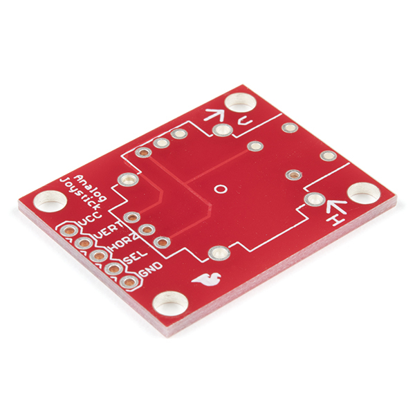
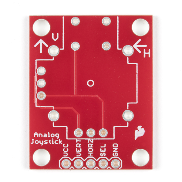
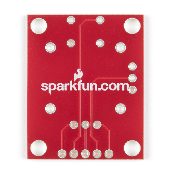
This is the breakout board for the thumb joystick. Pins are broken out to a 0.1" header and includes 4 mounting holes in the corners.
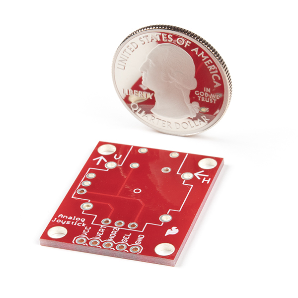
- 1" x 1.25"
SparkFun Thumb Joystick Breakout Product Help and Resources
BadgerHack: Gaming Add-On Kit
February 16, 2016
Make a Breakout clone with the BadgerHack Gaming Add-On Kit.
Thumb Joystick Hookup Guide
February 20, 2019
Whether you're blasting aliens, driving a robot, or write your awesome classic Arcade Game for your Arduino, you'll find the analog thumb joystick a very useful addition to your projects!
Qwiic Pro Micro USB-C (ATmega32U4) Hookup Guide
February 6, 2020
An overview of the ATmega32U4-based Qwiic Pro Micro USB-C, how to install it, and how to use it with Arduino.
Core Skill: Soldering
This skill defines how difficult the soldering is on a particular product. It might be a couple simple solder joints, or require special reflow tools.
Skill Level: Noob - Some basic soldering is required, but it is limited to a just a few pins, basic through-hole soldering, and couple (if any) polarized components. A basic soldering iron is all you should need.
See all skill levels
Comments
Looking for answers to technical questions?
We welcome your comments and suggestions below. However, if you are looking for solutions to technical questions please see our Technical Assistance page.
Customer Reviews
5 out of 5
Based on 10 ratings:
1 of 1 found this helpful:
Nice
easy to use!
Handy
Makes using joystick lot easier!
Fantastic!
I bought this breakout to make my first soldering project. It was super easy to solder and looks great! It's a necessity if you're trying to experiment with an analog joystick.
spark fun is great
Several years ago I sent in a comment about how the joystick breakout board did not have mounting holes. They took my comment and redesigned the board. I have now bought 4 sets of the breakout board and ps2 joystick. I used to pay over $100 for a joystick that these two parts replace for under $10. Thank you sparkfun!
Worked Perfectly
I was able to solder the joystick with no problem and it's much easier to use with the Arduino now. If you are getting the joystick you'll want one of these too.
Worth the $2
If nothing else, it makes sorting out the Thumb Joystick's pins a breeze. Each of my small stash of joysticks has one of these waiting for it.
Bought for beginner controller modding
The corner holes and the small size of the board make it a great fit for this kind of project. You can use the corner holes to mount the board on a 3D print and glue the joystick in place for a secure and easy-to-build custom joystick. Also, the joystick that accompanies this board is the ALPS RKJXK122400Y analog stick. ALPS is the company that makes joysticks for all three gaming giants, so you can trust that the stick is quality (or, at least of the quality you would get in a controller) is the same. But, good luck finding it for a better price than Sparkfun, because ALPS themselves sells 'em for $10.
Much better than standard Amazon/Aliexpress fare
Didn't have to remove the headers that won't work in almost every actual use case. Can solder control wires directly to pcb.
It fits
A little tricky to get all of the joystick contacts lined up, but it fits and makes connecting to the joystick far easier than trying to connect individual leads and the mounting holes on the corners are very convenient. It's a cheap and effective way to wire up a joystick.


How long will it take for this product to be back in stock?
You have an estimate of negative 39 pieces, ha ha...that's not good.
Is there any reason SEL is connected to GND when pressed and the digital input has to be pulled-up ?, I mean, when checking Arduino.cc tutorials, in their examples the pushbuttons are connected to Vcc when pressed and their digital inputs pulled-down.
Technically it really doesn't matter much but the Arduinos (and many other microcontrollers as well) do have internal pullups meaning if you connect things to ground you don't actually need to add a physical resistor.
In case anyone is interested (and I hope I'm not stepping on any toes here), made a quick eagle file for a dual joystick (same as this, but doubled on one breakout). Get it on github if interested: https://github.com/Stef-D/dual-joystick-breakout
Not stepping on toes at all! Thanks for sharing with the community :)
Sparkfun, could you create a modular breakout holder? Something that could combine multiple breakout boards to make a "super" sensor shield for Arduino or other platforms?
Can this be adapted to make a joystick mouse for a laptop. Maybe even wireless?
Not sure exactly how to describe this. When I mount the joystick on the breakout board, then put some standoffs on the component side, the joystick's skirt interferes with two of the standoffs. The standoffs are the small hexagonal threaded standoffs, 4-40 threaded, 1/2 inch long. It would help to move two of the mounting holes (the top two, looking at the photo) about 2mm "north". Maybe I will nibble away some of the skirt to provide some clearance, geometry permitting.
I just stepped on this rake myself. Went to mount the breakout board with 5/8" long 4-40 standoffs and discovered that the joystick "ball" and the two standoffs at the switch end of the breakout board want to occupy the same space, wonderful, more things to make and the clock is ticking.
Mount from below, if you can.
An alternative if you must mount on the front/top cover of your project, albeit a hack, is to mount the joystick on a thin piece of aluminum that is 1/4" or so wider than the breakout board, and then mount the assembly as needed. This will get the standoffs away from the ball of the joystick.
can someone help me out here? on the fourth example picture, there are little legs coming out of the gnd, sel, etc. pins of the board. what are those called/where can i find them?
Those are commonly called "headers", and you can find them (both straight and right-angle) in the related products below.
any eagle files for this? I am looking for the hole spacings so I can mount it correctly. Otherwise great very handy product.
could you post the eagle files for this? or possibly give some dimensions on the board and the joystick? Specifically the mounting hole spacing....
For use with this breakout board, it would be very useful to have a right angle version of the 5-pin polarized header you offer here: http://www.sparkfun.com/products/8230
The straight header interferes with the motion and click of the joystick. An example of what I need is here: http://www.futurlec.com/Connectors/POLHDRR5.shtml
Will you be making any revisions to the board soon? I used this in one of my projects and it worked great!<br />
<br />
However, I am not using any micro controllers in my project and to use the Select button was a bit of a chore. I was using a dual NOR gate as an SR flip-flop and I needed to limit the current to the microswitch with a 10K resistor. Because the microswitch is tied directly to ground I had to cut the trace for the microswitch ground and route a 10K resistor along side it. <br />
<br />
Is there anyway that future versions could have a provision for current limiting resistors, for analog electronics?
An interesting form of user input. I have measured what the matching joystick can do and documented it, available at: http://wp.me/pQmjR-h8
I got both the thumb stick and the breakout board. The Vert and Horz were pretty easy to use since they are just the voltage division value based on the Vcc. If Vcc in 5V, then the center position is 2.5V. I don't know the rating on the potentiometers so it's probably safe to not put too much voltage across it. I tried 3.3V and 5V and you get more voltage resolution with the higher voltage.
The SEL wasn't as straight forward. I thought when you push the button down you just get Vcc at Sel, but it's actually the opposite with the way the PCB is made. You get "GND" at SEL. I think you could just reverse the GND and VCC to give SEL a logic high. However, all you Horz and Vert voltages will be backward. Anyway, I kept the wiring the way it was intended and just hook select up to a load with Vcc on the other end. I put an I/O pin from an MCU at SEL to check for logic change to low and that works fine.
This thumb stick and the breakout board are great! I now have my servo controllable with the thumb stick and I use SEL to change from fast speed to slow speed.
"I thought when you push the button down you just get Vcc at Sel, but it's actually the opposite with the way the PCB is made. You get "GND" at SEL."
thanks so much... i thought my joystick is broken after soldering it to the board... after setting the input pin to HIGH in setup and checking it for getting LOW it works. didn't even thought that it could become LOW... thank you!
I just got this recently and used it to hook a thumbstick I removed from a PS2 controller to my arduino. Works great, easy to use, thanx guys. I made a quick test video here if you want to see it in action: http://www.youtube.com/watch?v=gvvu--1sdhg
The photos are inconsistent, as some show holes in the corners and some do not. Also, I'd like to order this and the matching joystick, but I've yet to see both in stock at the same time. It's a bummer to have to pay for shipping twice just to get these two items (not to mention the colossal waste of energy shipping two separate packages across the country.)
you can click the little box to have the order held until all items are available.