Button Pad 2x2 - Breakout PCB
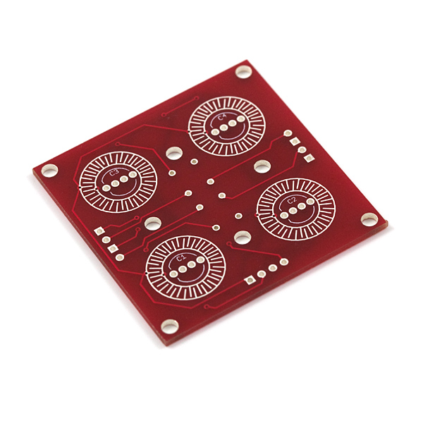
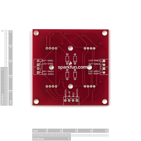
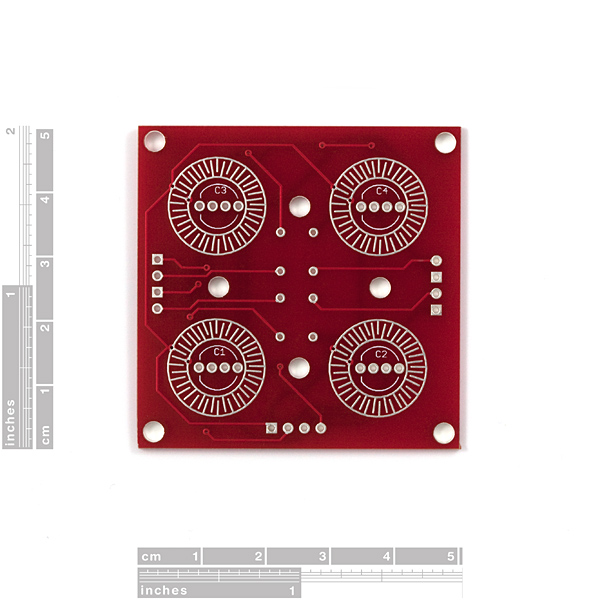
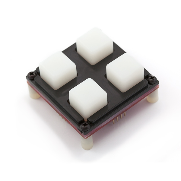
This a simple breakout PCB for our 2x2 silicone button pads. Each LED and button is brought out to the side connectors. The connectors are soldered to the back side of the PCB. We recommend trimming the connector leads on the button side as short as possible to reduce the deflection of the pad.
Now with footprints for diodes! Use the super cheap 1N4148 through-hole diodes. These can be used to isolate the switches to make for a bit easier decoding.
Button Pad 2x2 - Breakout PCB Product Help and Resources
Core Skill: Soldering
This skill defines how difficult the soldering is on a particular product. It might be a couple simple solder joints, or require special reflow tools.
Skill Level: Rookie - The number of pins increases, and you will have to determine polarity of components and some of the components might be a bit trickier or close together. You might need solder wick or flux.
See all skill levels
Comments
Looking for answers to technical questions?
We welcome your comments and suggestions below. However, if you are looking for solutions to technical questions please see our Technical Assistance page.
Customer Reviews
4 out of 5
Based on 2 ratings:
It's quirky...
All of the other comments and reviews are pretty spot on. The blue and green are flipped if you use SF's recommended RGB LEDs and the diodes aren't really necessary.
I wanted to use the buttons with a Frightprops boobox and had to remove the diodes to get the button inputs to work properly (if you read this first and happen to be doing the same thing, you can reverse them instead. I just used jumpers.)
The other weird thing is that on half of the board the green in the LEDS is "paler" than the other side. It's consistent across all the boards and LES (as I bought two) and it's only with the green color. One side of the board makes them lighter and the other side makes them a more deeper true green. (Even without the diodes in place)
Despite all that, they do what they are supposed to but it requires some research to make sure it's not broken.
Button Pad 2x2 Breakout
I purchased these for my grandson. He says they are great. He was able to do the job he had in mind. He is 11. He has joined two of them and has the output wired to a frequency generator which now has an octave of notes.

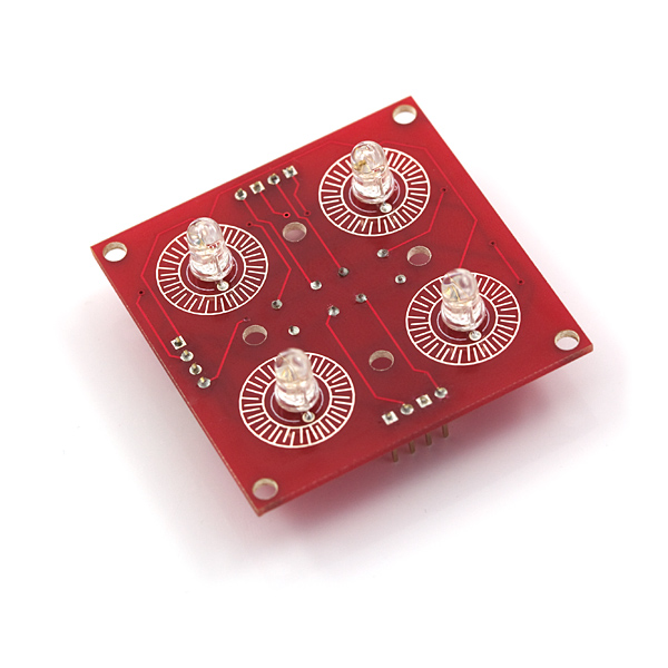
OK, so with a little knife and solder work, I was able to use the addressable LEDs. Man, they are cool. I think SF should really consider recreating this board, and the 4x4 with the addressable LED layouts, especially if they can somehow make it difficult to buy the wrong one, or the wrong LEDs. Maybe they could put a few vias in so you can do some quick soldering to convert them. Once you see this work, with just one microcontroller pin, you'll see what I mean. I think I'm going to have to look into wiring several of these up as neighbors to make a big fat button display.
Anyway, this is how I did it. With the addressable LEDs, the middle two pins are gnd and VCC, those need to be wired across all the LEDs the same. If you make the flat side of the LED line up with the silk screen, then the VCC is already all connected as the "BLUE". You have to solder all the grounds together.
Then, you can look at where the traces are going on the board, and cut them so that the "GREEN" and "RED" channels are all completely disconnected from each other. This is because the "GREEN" of each LED is DIN and the "RED" of each LED is DOUT. So you need to wire the first DIN to your microcontroller, and the first DOUT to the second DIN, etc. I wired the last DOUT to another PIN, just so it wouldn't have to be a dead end.
The traces are all pretty big, and you can cut them with an xacto knife. I just scraped a couple of mm out, and then tested with a multimeter. They are also really easy to see.
I've always wished Sparkfun would create an addressable LED version of these boards, but they sadly do not offer it. I've contemplated doing the same as you, cutting traces and re-routing, but I wanted something a bit more finished looking, so I've created an exact replica of this board so it will allow the use of such LEDs, and it's available on OSH Park. I've made it so that the LED portions are chainable if necessary so one can daisy chain these if needed as well. Shipped free, they're $19.35 for a set of three, (6.45 per board, but 3 is the min order), which is a bit more than what Sparkfun offers, but these are ready to go if anyone is interested. Just note that these take a bit longer to arrive.
These boards are completely made from the ground up, using available dimensions for the holes and the button contact locations. The silicone buttons fit perfectly and work exactly the same. I've also managed to increase the resolution of the button contact grid, and due to being from OSH Park, all exposed copper comes gold plated, and these improvements make the button contacts more reliable... (I've had instances where the Sparkfun button contact surface oxidizes over time, causing me to take apart projects and clean the contacts, which is about once a year or so). These are designed to use the SJ-F5-2811-F LEDs (5mm), That Sparkfun offers, or equivalent, (basically, use Adafruit's NeoPixel Arduino library / tutorial).
NOTE: The diodes ARE NOT necessary unless creating a scanning matrix with multiple button boards. Simple jumpers are all that is needed if using single boards for projects.
I just came back here to suggest again that they should make this board. I am happy to order it in purple though. Thanks for doing this!
I should have read all the comments before. Don't add the diodes! They prevent from directly connecting to pull-up pins. And because the layout is not a matrix, they don't serve any purpose. In fact I don't understand why they were added.
I was wondering why SFE doesn't have a kit version of this, that comes with all the necessary hardware, which would include the board, LED's, button pad and bezels. It would be much easier to buy just the kit, and I'm sure it would save customers and maybe even the SFE team some time in getting orders together.
Yeah, even a public wish list would be nice.
I made one
I was confused about the "bottom" bezel for a bit, turns out you only need two of those and two of the "top" bezels for the 4x4 matrix. They interlock together to keep you from having too many screws... clever.
You only need one of the "top" bezels for the 2x2 matrix. And if you have 4 inputs on your microcontroller, you can use the 2x2 button pad pcb without diodes. Just jumper the diode spots with a wire, and connect the "cathode" side of your jumper to GND with software pulls-up on your micro inputs. Thanks for the list @Shloimy ;-)
judging by the pinout i found that the buttons are not in a matrix formation but as regular buttons. so the diodes are not needed at all.
I realize this was 4 years ago, and you're correct; but for anyone ordering this, you still need a jumper to bridge those holes together. I used 0 ohm resistors because the size was convenient... and what else am I gonna use them for?
And now 8 years after this comment, I am still confused and I didn't understand the schematic. Mine is wired up to a known working program on an arduino, the pins are all correct, but nothing happens on the button pad board. if i have 2 of these with 8 buttons, does each pin go to the "swt" hole on the PCB? for wiring the two together, does the green hole on one go to the green hole on the next and then to the appropriate pin?
Did you figure out the button pad? I have no response on button pushes.
I have created a sort of tutorial / example for this. I have included a schematic, breadboard layout, and two versions of the sketch that I wrote. There is also a video attempting to explain how things work. This mainly covers controlling the LEDs, but the sketches also include input code.
http://www.aarongoselin.com/active-posts/28-using-sparkfuns-2x2-rgb-led-button-pad-with-an-arduino
It hopefully will make life easier for someone who is as new as I am :)
It seems that the Eagle files for this are a bit off. I recently made a video using this board and it turns out that the names of the signals going to the connectors aren't named properly. For instances, the signal next to SWT-GND1 silkscreen is actually SWT-GND2, and its the same for the LED-GND signals.
I know this is an old board, made by the CEO himself ages ago but it is just something to note.
It would be nice to have this breakout board layout for https://www.sparkfun.com/products/12986 [LED - RGB Addressable, PTH] Then chain a few together .
i'm not sure why i find this board so confusing, particularly controlling the LEDs. it would be great if sparkfun released a version that would work with the addressable LEDs so we could use the neopixel library.
Im thinking... wouldnt it be nice to have this awesome panels but with those nice WS2812B leds instead of regular leds? That way you could control a lot of them with just a few pins of the micro or arduino!
I am looking at a mod that will allow me to use the PTH 5mm Neopixel LEDs. That would be better and far less pins. I will post any updates.
Hi, it would be really useful if the schematic for this was actually available.... I've just ordered this, and all other parts to create the button pad, and I'm now at the point of setting it up in arduino. I'm familiar with using the RGB LED's from a previous project, but looking at this board I have no idea how I'm supposed to control the colour of each LED independently. I'd really appreciate some advice from anyone else who has done this, on both circuit and sketch. Better yet a tutorial would be amazing. As I stand now, my code is set up to use analogWrite to change the brightness of each LED leg, but I don't think that's how this PCB does it. It appears to be PWM, which I understand the principal, but not how to use.
Thanks in advanced. Joni
Hi! The schematic is actually available, although I can understand if it's a bit difficult to read (it uses a bus - not a fan of those myself for smalls scale projects). If you look at the top left of the schematic, the 'connector' (set of solder pads) indicated as JP1 are your 'common' lines. The connectors at the bottom are the individual lines for each button/LED area.
Let's say we tackle the buttons first. The switch pin from JP1 would get hooked up to your Arduino's Vcc. The switch pins from JP5, JP6, JP7 and JP8 could go to individual I/O pins (can be digital-only). You would add some resistors to pull the level on those pins down to ground by default. That way if you read the pin, it'll either be low (not pressed), or high (pressed). Another option, however, is to use a single pin which you can use analogRead on. You would do this by setting up a voltage divider network with non-overlapping resistor values, one for each button. That way when you read a certain analog value, you'll know which button, or even which buttons, are pressed.
For the LEDs (assuming Common Anode ones), you would connect each of the LED pins from JP1 to PWM-capable pins (3 in total, one for each color), and the LED pins from JP5-8 to other pins (can be digital-only) (don't forget appropriate resistors!). Quick note: PWM is the same as analogWrite. Arduino doesn't actually write analog values, it just sends a PWM signal which - if it were to be integrated perfectly - would yield an appropriate analog value.
Let's deal with just 1 LED right now, LED1, which uses the 3 pins for each color, and the pin used for LED-GND1. If you set LED-GND1 high, then it doesn't matter whether the pin for a color is high (no voltage potential) or low (voltage across the LED is in the 'wrong' direction), the LED will not light up. However, if you set LED-GND1 low, then whenever the pin for a color is LOW, the LED will still be off, but when the pin for a color is HIGH, the LED will turn on. PWM/analogWrite just sets the pin HIGH/LOW/HIGH/LOW/HIGH/LOW etc. very quickly, so the LED turns on/off/on/off/on/off etc. very quickly, allowing you to set different intensities.
Now here's the rub. Let's say you set LED-GND1 low, and you set LED-GND2 low, and set a pin color high. Now both LED1 and LED2 will turn fully on. This is important for 2 reasons. Reason 1: you're using more current, all sourced from that single pin. Again, make sure you use resistors to limit current - not just for the LEDs, but for the pin as well (push comes to shove, use transistors for the color pins instead). Reason 2: What if you wanted LED1 to be fully on, and LED2 to be more dim? You can't do both at the same time, so in your code you would have to loop over each LED, setting the LED-GND1 pin low while at the same time setting its color pin high, then setting LED-GND1 high again, setting LED-GND2 pin low while at the same time setting its color pin to a more dim value (analogWrite), setting LED-GND2 high, and so on. As long as you do this really fast, you wouldn't generally notice it other than that each LED is a slight bit dimmer as they're off for 75% of the time when using all 4 LEDs - on the up side, you also avoid the extra current being sourced from the color pin, as only 1 LED at a time is actually lit.
This may still seem like quite a few pins being used, if you wanted to reduce that (especially if you had the 4x4 button board), you'd have to look at shift registers for multiplexing or even dedicated LED driver ICs :)
Note: This stuff always makes my brain hurt when I don't have an Arduino in front of me, so there's always a chance I messed up some logic up above.
Hi again Kamiquasi, I've been doing my best to read through what you wrote. I understand the principle of using the buttons (I think), particularly reading whether a switch was pressed. What do you mean add resistors to pull to ground? Also where does this resistor sit in the circuit (between 5v and button or button and I/O?) and what resistance should it be? I might be able to work out the resistance, except I don't yet understand what pull to ground means. Since we are on the topic, your advanced example of using one pin and different resistance values, resulting in a way to determine the button press by analogueRead. Would you kindly give me an example/explain how to figure out what resistance these resistors should be for this method?
RIGHT! That's my buttons q's! Now for the hard bit. LEDs... First I'd like to note that my RGB leds are common cathode. I assume that just swaps around some pins/brightness values? Without the schematic, I'm finding it tough to follow, but trying none the less. Like with the buttons, is JP1 a shared connection for the LED's? Where you lost me was the last paragraph. So without the schematic I'm assuming that there are only 2 LED-GND? for each column? Hence your advice about controlling 1 or 2 at the same time. The bit I don't understand is the controlling of just one LED at a time. I'll explain my hopes and perhaps that might help. I'm trying to implement a popular arduino project: RGB combination lock. I'm tweaking it slightly, so that instead of stationary colours for each button, I hope to move the colours around, so the combination depends on a colour, not a button. On that note, they clearly need individual control, and to all be as equally bright as possible. I hope that made sense. If you need more info on the project: http://hackaday.com/2008/06/12/how-to-make-an-rgb-combination-door-lock-part-1/ just note that I'm not using a digital potentiometer, only the arduino and the button + rgb leds. Whilst writing this I've got an email about another post of yours regarding the schematic so I appologise for bringing it up again in this post. I'll be sure to view the screenshot. Thanks again! You're really helpful. Joni
Hi Joni,
Let's start with the button/resistor bit - the Arduino site actually explains this one pretty well :) Arduino - Button.
The resistor divider network thing is something I've personally never used beyond 2 buttons, but there's a whole thread of comments in: Keypad - 12 Button. Basically you'd want to use different resistor values so you can determine which single button is pressed, but also ones where the read values remain unique if you press multiple buttons at the same time (creating parallel resistances). I say 'basically' but as you can tell from the length of the thread there, that's not the most immediately simple thing :) (Though they've got 12 buttons to deal with, 4 is considerably easier).
The LEDs being common cathode doesn't immediately matter, no - you'd still set pins low/high and the LED will only light up if its cathode is low, and anode is high :)
I see where some of your confusion stems from. I think the first thing to realize is that this button pad does not actually have a columns vs rows setup at all. In your case, all 4 LEDs' RED anode pins would be together on JP1, and the same with green and blue, while each of your LED's cathode pins run individually to one of the 4 other connectors (JP5-JP8). So if you wanted to light up just LED1 in red, you would make sure that the RED anode pin is HIGH, and that the LED1 cathode pin is LOW while the LED2, LED3, and LED4 cathode pins would be HIGH.
The tricky bit is if you also want LED2 to be GREEN. You'd have to set the GREEN anode pin HIGH, but because LED1's cathode pin is LOW, LED1 would light up yellow (red and green). So you would first have to sett LED1's cathode pin HIGH to turn it off, and then set LED2's cathode pin LOW to turn LED2 on. ( You would also have to set the RED anode pin low or else LED2 will light up yellow).
In code, I suspect that the best way to handle this would be to have an array of each LED's colors that you want to set, and then in the main loop handle toggling which LED gets to be on (1, 2, 3, 4, 1, 2, 3, 4) and set the color pins as appropriate for that LED. This would naturally make them all equally bright as each LED is on for the same amount of time :)
Wow you're great at explaining this. Can't tell you how grateful I am. You've cleared up the button resistance for me completely, thanks, With the LEDs, does that mean that I need to very quickly switch between the specific setups for each LED + colour? Can the arduino do that fast enough to achieve the result and trick the eye? That's pretty clever. I imagine then that this only works with small(er) amounts of LEDs, since if I add more LEDs, they have a greater off time? Any idea how long I need to make the time between each colour switch? Or perhaps how many LEDs this would work with?
Your help is awesome, thanks. Joni
That is correct - you have to switch between the LEDs. The Arduino can do this plenty fast enough that you won't normally notice the flickering except when you shift your sight. If you've ever looked at a car's rear lights and saw multiple 'copies' of them whenever you'd look around, but then didn't notice anything special about them when you just looked right at the car, you've seen pretty much the same concept - your eyes are generally too slow to notice that the LEDs are actually blinking. What you do notice compared to an LED being on all the time, though, is that it's a bit dimmer. It doesn't quite work out to a case of "If it's on half the time, it's at half the intensity" because human vision is funny like that, but dimmer nevertheless.
You are also spot on with deducing that given enough LEDs, you would, in fact, start seeing blinking :)
I'm not sure how much time you'd need, as that largely depends on what else you're doing in your code. A forum post elsewhere suggests that if you've got nothing in your loop except for 2 digitalWrite commands, then the loop itself runs at 130kHz. That's many, if your LED were only on for 1 out of 4 of those loops, that's still 32.5kHz - many, many times faster than you'd be able to notice :) But, again, this really does depend on what else you're doing.
Kamiquasi thanks so much. Glad to hear I was on track with my assumptions. At least a degree in computer science pays off a little! My buttons and pcb breakout should arrive in the post this week, delivered from sparkfun to the UK where I live, so I've been on the edge of my spinning chair waiting! You've cleared it all up for me, and I'll be sure to post my progress, in the hope of helping others. Thanks again, Joni
Good luck! And if I've got it all wrong, make sure to one-up me and post the correct usage :D
Kamiquasi thanks again! I'm very appreciative of your advice! I'll have to read that a few times I think, as I'm fairly new to electronics. Sadly if I click the schematic link, I just get a blank page. I've obviously allowed it time to load, and checked even the zoom etc.. but just blank for me. I definitely appreciate that you are guiding me on the proper way to tackle this, and also the proper way that this PCB is intended for, but are there enough pins on the Arduino to wire each LED individually? Seeing as most of the pins can use analogWrite(), I calculate that 4 x 3 pins will easily fit on the Arduino. And then a further four for the buttons should fit as well. I may try to wire them up in the most simple fashion until I can fully understand your previous post. Unfortunately I learn better with pictures than writing so it may take me a while to understand you ;) I'm a firm believer of learning over copying however, so I'll try my best before posting again if I have to. Again thanks, I really appreciate this! Joni
I am confused, is this laid out for common anode or common cathode RGB leds?
Schematic suggests common cathode, but as far as I can tell from the schematic and PCB, you could use either one. Just keep in mind that the silkscreen on the board reads 'gnd', so you might want to scratch that off to prevent any confusion if you do happen to use common anode LEDs.
Anyone have any example code using this? I'm not sure exactly how to use this thing
Take a look at this Wiring example. This board simply allows you to drive multiple RGB LEDs simultaneously.
I bought the COM-09264 RGB LED to go along with this PCB, and the holes are too far apart to allow the LED to seat low enough for the buttons to work.
It will be necessary to really pull and contort the outer leads in order to bring it down, and I am afraid that will put too much strain on the LED leads where they enter the epoxy.
Am I missing something here? Perhaps I ordered the wrong LED? What gives?
i don't know what i'm doing wrong, but i'm not getting this to work. does anybody know of an arduino tutorial that shows how to use the buttons as isolated switches? i'm at my wit's end.
I'm having a few issues as well. I'm just using the guide Nakor gave up above from 2 years ago
Any chance SFE could start carrying RGB LED's that had common anode? I bought this pad (along with all accessories and the diffused RGB LEDs from SFE), and I'm using a TLC5940 to connect two of these boards. The TLC5940 can only sink current, so I spent days trying to put a square peg into a round hole. Would be good to have a tutorial or page on this product page listing the differences between common anode and common cathode (which I know now) and also cautioning users to double-check the specs of the LED driver they plan to use. Now for a lot of not-so-fun desoldering and replacement with common anode LEDs from another vendor....
Any chance of adding documentation (sample sketches, etc.) for this? I've spent hours searching for how to wire and control this thing, but I haven't had any luck.
This is a truly passive device - you should be able to use an ammeter and some sharp probes (or trace things out with a sharpie) to figure out where everything connects.
On the PCB I received, the blue and green pins were labeled incorrectly. I assume I was given a board that was produced before the problem was solved, but I just wanted to confirm that SparkFun (and customers) are aware.
We switched LED suppliers and they have different pinouts. Not all RGB LEDs have the same pin designations.
Okay, thanks for clearing that up. I gotta say though, it makes more sense to me to have red, green, and then blue. Unless they're advertised as RBG LEDs.
Seconded.
I would like discreet control over each led. Is the only way to scan the leds? Or cut traces?
Would it be possible to add some holes for capacitors on the led lines? I think they would be useful for cutting down on the flicker since you have to scan the channels and colors.