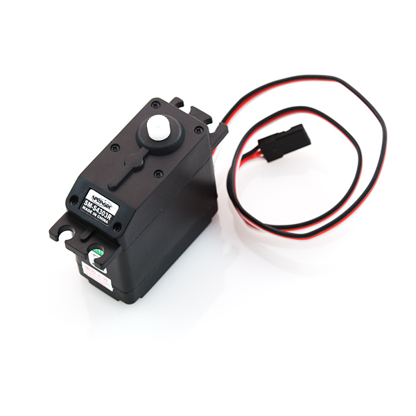
Servo - Generic High Torque Continuous Rotation (Standard Size)
Here, for all your mechatronic needs, is a simple, high quality continuous rotation servo motor. This servo is able to take in 6 volts and deliver 66.7 oz-in. of maximum torque at 70 r/min.
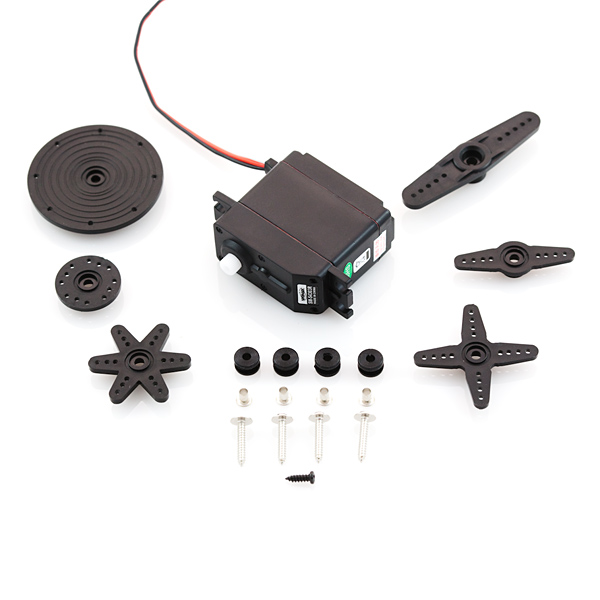
A standard 3-pin power and control cable is attached and all hardware listed below is included.
- 1x SM-S4303R High Torque Continuous Rotation Servo
- 1x Mounting Screw
- 1x Four Point Horn
- 1x Six Point Horn
- 2x Double Arm Horn (1x Large, 1x Medium)
- 2x Circle Horn (1x Large, 1x Medium)
- 4x Rubber Grommets
- 4x 2x15mm Phillips Screw
- 4x Brass Eyelets
- Voltage: 4.8-6.0 Volts
- Torque: 45.8/66.7 oz-in. (4.8/6.0V)
- Speed: 60/70 r/min (4.8/6.0V)
- Rotation: 360°
- Dual Ball Bearing
- 4 Plastic Gears + 1 Metal Gear
- 25T Spline
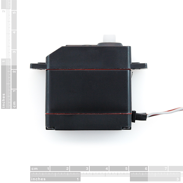
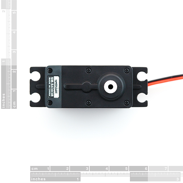
- Rest point adjustment* 42 x 39.5 x 22.5mm
- Wire length: 300mm
- Weight: 44g
Servo - Generic High Torque Continuous Rotation (Standard Size) Product Help and Resources
Servo Trigger Hookup Guide
March 26, 2015
How to use the SparkFun Servo Trigger to control a vast array of Servo Motors, without any programming!
Hobby Servo Tutorial
May 26, 2016
Servos are motors that allow you to accurately control the rotation of the output shaft, opening up all kinds of possibilities for robotics and other projects.
Continuous Rotation Servo Trigger Hookup Guide
May 26, 2016
How to use the SparkFun Continuous Rotation Servo Trigger with continuous rotation servos, without any programming!
LED Gumball Machine
April 24, 2019
Hacking gumball machines to make the world a happier, blinkier place.
Stall Current
A tech support representative tested the stall current on this motor. Here are the results:
- 860mA @ 4.8V
- 1.05A @ 6V
Power Supply
Make sure that you use a separate power supply that is sufficient enough to power the Generic High Torque Continuous Rotation Servo. 5V from a computer's USB port and Arduino microcontroller will not be sufficient enough to power the system. The servo can pull enough power to brown out your Arduino or not move the servo.
Core Skill: Robotics
This skill concerns mechanical and robotics knowledge. You may need to know how mechanical parts interact, how motors work, or how to use motor drivers and controllers.
Skill Level: Competent - You may need an understanding of servo motors and how to drive them. Additionally, you may need some fundamental understanding of motor controllers.
See all skill levels
Core Skill: DIY
Whether it's for assembling a kit, hacking an enclosure, or creating your own parts; the DIY skill is all about knowing how to use tools and the techniques associated with them.
Skill Level: Noob - Basic assembly is required. You may need to provide your own basic tools like a screwdriver, hammer or scissors. Power tools or custom parts are not required. Instructions will be included and easy to follow. Sewing may be required, but only with included patterns.
See all skill levels
Core Skill: Electrical Prototyping
If it requires power, you need to know how much, what all the pins do, and how to hook it up. You may need to reference datasheets, schematics, and know the ins and outs of electronics.
Skill Level: Competent - You will be required to reference a datasheet or schematic to know how to use a component. Your knowledge of a datasheet will only require basic features like power requirements, pinouts, or communications type. Also, you may need a power supply that?s greater than 12V or more than 1A worth of current.
See all skill levels
Comments
Looking for answers to technical questions?
We welcome your comments and suggestions below. However, if you are looking for solutions to technical questions please see our Technical Assistance page.
Customer Reviews
4 out of 5
Based on 6 ratings:
2 of 2 found this helpful:
Solid device
Does what it's supposed to do. Easy to connect, easy to use. Goes well with Arduino-based projects as well as other applications. Works great as part of a home made useless machine project.
1 of 1 found this helpful:
More Than One
We bought multiple units for our elementary robotics club, two of them are working great, one is not. They were all doing the same task on the robots but one of them the gear stripped out in no time. The other two held up under a day long Robotic Expo and were easy to use. Don't know if I just got a dud with the other one. Over all they were dependable and easy to mount.
Sorry to hear you might have received a bad unit. Please contact us and we'll be happy to help you out - https://www.sparkfun.com/technical_assistance
1 of 1 found this helpful:
All of the students want to use it!
Students found that this versatile servo really fit the needs and functions of their projects.
Exactly what we needed
We bought 10 of these servos to use as "drive motors" motors for student design and built mini robotics platforms to be RC and/or Arduino controlled. Worked out perfectly. plenty of power for our application.


Is there any coupler for this servo to attach 1/4" shaft? Does anybody know?
Some details about (hobby) servos that suppliers almost always leave off their websites (please correct me if I get something wrong [might be good to add some of this to the description...or throw in a tutorial])...
Servos are (usually) DC motors that allow you to control the angle of the axle. The way they do this is by packaging a motor, potentiometer, gears, and a small circuit board in a plastic case. The pot and motor are attached together by gears and the electronics attempt to use feedback from the pot to maintain a position with the motor.
Servos are controlled by pulse width modulation on the control line. Details of how PWM works are easy to find online, but the frequency and duty cycle/actual pulse duration for hobby servos is rarely right there beside the ad for the servo... (I think this is actually because most people that use servos use them in pretty standard hobby situations like RC airplanes. And for those applications all of the PWM is taken care of by other hardware) Fortunately because of these standard application the PWM details for most servos are the same if you're like to do it the fun way...
Frequency: 30-50 Hz (not a set number I know...if the servo buzzes try adjusting this up or down... you can squeeze it to just outside the pulse width range of your servo and maybe get better response times...)
Pulse width: .9-1ms = all the way one direction, 1.5ms = center range, 2-2.1ms = all the way the other direction.
Unlike other small DC motors PWM on the control wire allows the actual motor in the servo to use all of the power of the other two wires, while the electronics and control line allow control. (Ground for the motor and control line should be tied together in your circuit, but the supply power could/should be a higher currect source (staight to the battery usually) than your average chip producing the PWM)
Normal Servo (ROB-09065 and ROB-09064) usually have a movement range of 90 degrees. You can get ones that do 180/360+ degrees.
Continuous Servos (ROB-09347) don't allow angle control. They simply spin in both directions and instead of angle control you get speed/direction control. The same PWM settings are used but in this case .9-1ms pulses = fast one direction, 1.5ms = stopped (sort of), 2-2.1ms = fast the other direction.
I'm sure PWM on the arduino is a breeze, in fact I know there are already libraries for servo control that let you just drop in an angle... If your slightly more hardcore you can drop your favorite uControler in a breadboard and look through the manual (I mean ask someone on a forum/irc channel) for PWM details...
...yay comment length limit...next time i'll use feedback, but as it was just in you news i couldn't resist
Note that, while this does have a 24-tooth spline, it's not compatible with the C1-spline accessories sold by ServoCity (or at least the sprocket I got).
Yes, I have the same experience. This definitely does not fit the ServoCity/Actobotics (now sold by SF, as well) 'HiTec' compatible accessories. Neither do some Spektrum servos I have.
Are they 'Futaba' compatible? I don't know...
This arbitrary lack of compatibility between seemingly interchangeable devices is frustrating to me as someone not otherwise in RC planes, etc.
I have a pair of these fellas on an educational robot platform (diy). They work great. I'm sending 'microsecond' commands from an Arduino - rather than angular commands - as it offers higher resolution.
1000uS is full speed forward
1500uS is STOP
2000uS is full speed reverse
...anything in between gives a proportional speed. Very handy.
We're looking to battery power this 'bot. Does anyone know what current they draw? (on the power supply lines not the signal line)
Cheers
120 mA at 5V for full speed unloaded. If you load it up, I got it up to about 250 mA before I decided not to break the thing.
120 mA at 5V for full speed unloaded. If you load it up, I got it up to about 250 mA before I decided not to break the thing.
Hi Beardy - thanks for this comment! I was having problems getting this servo to actually stop.
myservo.writeMicroseconds(1500); //Stop servo
Worked great for me. Thanks again for pointing me in the right direction!
I put together a program that demonstrates how the pulse width controls the SM-S4303R servo. Thought you might like to share it with your customers:
https://www.khanacademy.org/computer-programming/pulse-width-demo/4961611581489152
Would it be possible to have 2 of these servos controlled by different light sensors in a Arduino board? So that sensor A triggers servo A and sensor B triggers servo B.
I don't see why not.
isn't it a must to use delay() to control the rotating time? So I guess they might not be able to operate at the same time. For say, when sensor B is triggered during the delay of servo A, it might not work?
You should be able to use the millis() function to approximate a delay without fully blocking execution. Just set up different timers/intervals for each of your motors and check the current time at each loop.
Oh, yeah, that gets a bit tricky. you can track time elapsed doing a while loop. but yeah, you're right, it does get a bit more complicated.
Does anyone know what weight this will support?
Also, any ideas on where to get wireless servos?
Does anyone know what weight this will support?
Also, any ideas on where to get wireless servos?
Be aware that although the flange is the same, the body on this SpringRC SM-S4303R servo is larger than the Standard Parallax/Futuba/HItec servos are. In my case the 0.1" added depth mattered. Check your design to be sure.
Be aware that although the flange is the same, the body on this SpringRC SM-S4303R servo is larger than the Standard Parallax/Futuba/HItec servos are. In my case the 0.1" added depth mattered. Check your design to be sure.
Be aware that although the flange is the same, the body on this SpringRC SM-S4303R servo is larger than the Standard Parallax/Futuba/HItec servos are. In my case the 0.1" added depth mattered. Check your design to be sure.
Be aware that although the flange is the same, the body on this SpringRC SM-S4303R servo is larger than the Standard Parallax/Futuba/HItec servos are. In my case the 0.1" added depth mattered. Check your design to be sure.
what would be the code for the IDE to make this motor go fully back and forward?
I need 60+ motors that spin continuously at exactly 1rpm for a project I am working on. Continuous rotation servos seem to be the cheapest option, but it's unclear whether I can get such a specific rpm. I am also wary about having to adjust the rest point all the time. Could this motor work for my application or is there another option?
Or a bunch of really small stepper motors. You could daisy chain their control together and command them all at exactly 1rpm.
Without some sort of speed feedback on each servo, it may be hard to get exactly 1RPM out of them. Can you use cheap battery-powered clock movements with second hands? They've been used for very lightweight (and slow) robotics before.
Could someone explain what the "Rest point adjustment" does. Thank you.
I have no idea what I'm doing wrong, but my servo won't move with less than 12V at 300mA from a wall wart. I've tried all sorts of sketches, including this one, but no changes to the variables make the servo stop or slow down. What's going on???
I have the power connected to the power rail of my breadboard, ground from arduino to the ground on the power rail, and the servo connected to the power rail with the white pin in arduino pin 9.
include
Servo myservo;
void setup() { Serial.begin(9600);
myservo.attach(9);
}
void loop() {
myservo.writeMicroseconds(1500); delay(5000);
myservo.writeMicroseconds(4500); delay(5000);
myservo.writeMicroseconds(7000); delay(5000); }
I hope you've found your answers before this, but if not: The servo PWM pulse is expected to be between 1000 and 2000 microseconds (average). Some servos will try to achieve positions between 500 and 2500 microseconds (positional servos may try even if they are physically incapable, so be careful!). Sending a pulse of 4500 or 7000 will just get ignored, as they are out of range. So basically you told the servo to stop (1500 = "center" for positional servos or "stop" for continuous rotation), then you sent pulses out of range that got ignored. One final note is that most hobby servos expect a 6000 to 9000 microsecond space between command pulses, and may not respond to changes from pulses sent before 6000 microseconds have passed.
Hope this helps!
I just bought two of these. I'm a beginner with this stuff, so I have a couple of questions. First I want to know if I can get feedback from this type of servo. I want to know the position (in degrees) of the servo. Second is there any way I can changes this servo so that I can control its range?
Same case here, I need position feedback for implementing odometry dead-reckoning on an Autonomous Mobile Robot. Have you figure out something already? You think we can explore the interior of the servo and take advantage of any circuit in there?
how precise are these? can i rotate a degree at a time?
This is a continuous rotation servo; it only changes speed and direction, you can't set angle.
nice information how to servo motor works.
What is the power consumption of this servo? I googled it and never found out. I want to connect it to my netduino in order to control a moving robot using wheels. I want to do the circuit between the servo and the netduino and it is necessary in order to choose the transistors, resistors and batteries
thank you!
how waterproof is this? I have an outdoor application and I'm wondering about rain/snow
How many milliamp's per hour does this draw? I need to know what battery to get.
@SparkFun: Torque is measured in forcedistance ie kgcm, not kg/cm. This is also what the datasheet states.
So, is kg/cm = kg*cm? I mean, how does this unit even make sense?
The / is equivalent to per, so kg/cm is equal to kg per cm.
[comment removed by author]
Both conventions are used. I brought this exact point up as well, but since both are used commonly, both remain on our site.
Does this use a standard Hitec or Futaba spline?
You've probably already found the answer to your question, but for other customers: this uses a standard Futaba spline (24 teeth).
Is it possible to buy the bits this thing comes with separately? (By 'bits' I mean the little propeller-type thingy and the round mounting bit doodad.)
Sorry about the technical language... If I'm not mistaken, a glossary of terms used here can be found on Wikipedia.
They are called servo horns or servo arms, and unfortunately we do not sell them separately. This is a standard-sized servo, though, so your local hobby shop can definitely help you out if you need some without buying a servo.
any idea when the next batch will come back in stock?
SparkFun How many milliamp's per hour does this draw?
I am working on a piece where I need to hook up 7, full rotation servo motors to the arduino (each rotating at a different speed, some in one direction, others in the other) but basically an on/off with a motion sensor. <br /> <br /> I amusing an infrared sensor but the servo is still moving (awkwardly and jerky) when not sensing motion, but then runs as normal.<br /> Here is the code I am using (right now, I am only at 1 servo � trying to get the sensor right first) :<br /> <br />
include <br />
<br /> Servo myservo;<br /> int potPin = 0; //analog pin used to connect the sensor<br /> int ledPin = 9; //select pin for the servo<br /> int val = 0; //variable to read the value from the analog pin<br /> void setup()<br /> {<br /> myservo.attach(9); //set up the servo as usual<br /> pinMode(ledPin, OUTPUT); //variable to store the value coming from the sensor<br /> Serial.begin(9600); //for watching the speeds in the serial monitor<br /> }<br /> <br /> void loop() {<br /> val = analogRead(potPin); // read the value from the sensor<br /> val = map(val,0,600,0,255);<br /> if (val>80) digitalWrite(ledPin, HIGH); //turn the ledPin on<br /> <br /> else if (val
Is the torque confirmed on this? If not, what is the source of this info?
The torque information is from the datasheet.
Do you have any wheels that we can mount on this continuous rotation servo? I didn't see any in your "Wheels" section. That would be quite handy.
I don't think that we sell any wheels that connect to this servo direct, sorry.
I ordered these when they were on sale, and tried them out as soon as I got them. They worked fine with the arduino sweep example, and I haven't touched them since I got them. Today, I got them out again to build a robot, and for some reason, neither of them work with the sweep example. One of them just buzzes without moving at all, and the other just continuously spins in one direction forever. Anyone know what happened?
While the servo is running/buzzing, use a small screw driver to adjust the 'rest point adjustment'. The motor should start running again.
I figured it out after I opened the servo, which wasn't needed.
If you want to see code samples for how to make these move at different speeds with any Aurduino, go here -
http://www.arduino.cc/cgi-bin/yabb2/YaBB.pl?num=1278145608
I successfully plugged in 4 at once to my Duemilanove on 4 different pins and ramped all of them up and down, backwards and forwards with the sample code at the url. No other driver/shield/h-bridge needed.
Grab some when they go on sale again!
here is a question, I havn't yet found an answer on yet:
Can you control the speed of these motors? My thought was (if it's possible) pulse widths further from the 0 position would result in a somewhat faster speed.
[zero position = no speed, max+ position = fastest in 1 direction, min- position = fastest in other direction]
Is this the case?
Figured it out after receiving one in the mail.
-Yes it does operate with speed control (using different PWMs)
Can this be modified to work as a normal position-control servo?
I would think it would be extremely hard to re-modify it back to a normal rotation servo. and i don't think it can be used like a normal servo because the position control hardware was taken out.
if you need just a standard servo with position control then i suggest: http://www.sparkfun.com/commerce/product_info.php?products_id=9064
If I want to operate this with an arduino (using the 9v 650mA wall-wart power) and I want the most possible torque, would it be safe to run it through the v in pin (voltage in, 9v 650mA) or am I restricted to the 5v pin?
Hi smb,
Yes you could but it would damage the servo if you operate the it above 6 volts
I just received this servo, I am using i with my Arduino. Connected it via the Servo class, every time I set the servo to angle 0 using myServo.(write); Zero becomes a spot on the servo. What am I missing?
OK...so I understand that the servo cant be set by angle, which isn't too important for what I need. How do I change the direction the motor is going? And the speed?
0 is full speed reverse 90 is stationary and 180 is full speed ahead. So 45 is half speed reverse.
How many mA's does this draw? can I run it right off an arduino pin (max 40mA)?
I think I answered my own question--the signal and power wires are separate. (new to servo land, sorry).
Mechanical drawing? Data sheet? Particularly, the nature of the output shaft? I would like to source gears to fit. Ultimately to operate lens controls (focus, zoom, iris, etc.). Maybe all servos have standardized shafts? But a mystery to those of us without R/C experience.
I have a Tower Hobbies Servo (made by Futaba) and the armature fit the shaft of this servo. Also, I look around on the web and it seems it's the same as Futaba output shafts (i.e. 24 tooth spline)
Datasheet: No idea, did a search for the model num from the pic: sm-s4303r
Drawing...
http://www.springrc.cn/en_index/view_list.asp?id=235&typeid=61
Gears...
http://www.servocity.com/html/servo_mount_gears.html
this looks like a pretty standard servo, but a non standard supplier...i dunno what to else to tell ya.
Is this a continuous servo, a regular servo with an extra-wide-range, or something else?
see my long comment below...in the last reply if you don't want to read the whole thing
That might be kinda handy to know...it is continuous.