JST Right-Angle Connector - Through-Hole 2-Pin
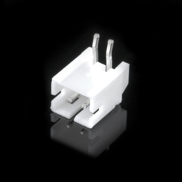
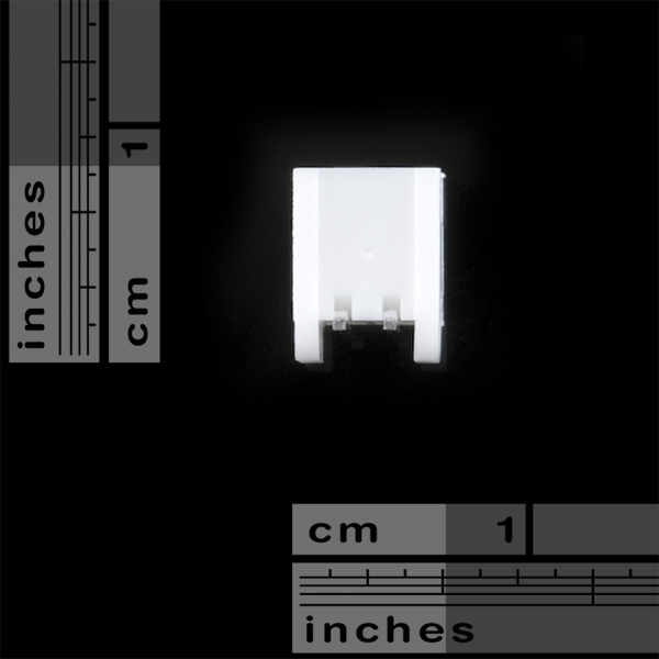
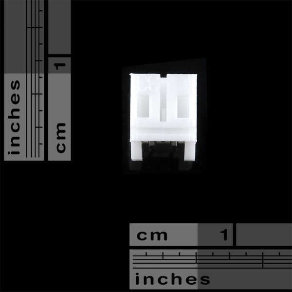
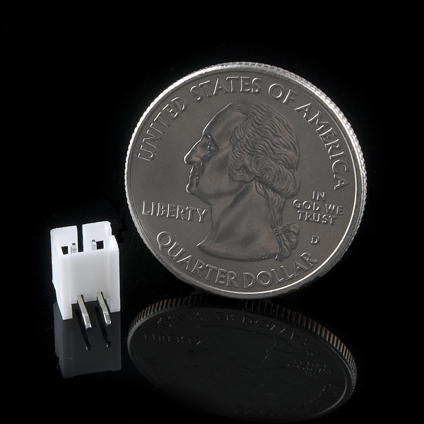
This is a 2-pin, through-hole PH series JST connector. The pins are spaced by 2mm.
We really like the solid locking feeling and high current rating on these small connectors. This connector will mate with all of our LiPo batteries.
JST Right-Angle Connector - Through-Hole 2-Pin Product Help and Resources
Connector Basics
January 18, 2013
Connectors are a major source of confusion for people just beginning electronics. The number of different options, terms, and names of connectors can make selecting one, or finding the one you need, daunting. This article will help you get a jump on the world of connectors.
How to Make a Custom EL Wire Extension Cable
October 24, 2018
In this tutorial, we will make a custom EL Wire extension cable as an alternative to splicing wire.
Single Cell LiPo Battery Care
March 16, 2023
This tutorial will go over how to safely charge, connect, disconnect, reinforcing the cables, and handle single cell LiPo batteries.
Core Skill: Soldering
This skill defines how difficult the soldering is on a particular product. It might be a couple simple solder joints, or require special reflow tools.
Skill Level: Noob - Some basic soldering is required, but it is limited to a just a few pins, basic through-hole soldering, and couple (if any) polarized components. A basic soldering iron is all you should need.
See all skill levels
Comments
Looking for answers to technical questions?
We welcome your comments and suggestions below. However, if you are looking for solutions to technical questions please see our Technical Assistance page.
Customer Reviews
4.5 out of 5
Based on 2 ratings:
1 of 1 found this helpful:
Not Just for LiPo batteries
I used this with a two wire JST cable to feed 5 volts to my project. (The 5 volts was produced from the output of a Buck-Boost converter.) So this worked great on a Prototyping breadboard. Did you know that the pins will also fit the same footprint as an LED? The board I used had an LED pad, which I didn't need. So I put this connector there instead. Instead of an LED taking power, this fed power into the circuit. And Sparkfun has the matching two wire JST cable too.
0 of 1 found this helpful:
it's a pain to plug batteries into
since there is no shell connections, there is no way you can hold this to a board other than soldering the two pins, you might have to try hot glue. other than that, its a good connector for li-po batteries


So am I correct in assuming this will fit in two adjacent pins on a standard .1" board like teensy/arduino mini/breadboard, etc? Or are they double that spacing?
The pins on these are spaced 2mm apart rather than the 2.54mm (1/10") you'd find on a breadboard, but you can bend them outward slightly and they will still work.
Beware! This part is in the SFE Eagle library, but it's poles are switched! Luckily I could just put the connector on the other side of the PCB.
The poles aren't switched, you are just mistaking the little "+" handle used for moving the components for a "positive" marker. I'll agree that's pretty confusing though!
Well, yes it is really confusing. But I see your point. If that is not the sign to indicate which is positive then there is nothing to indicate it. I'm hoping it's your not supposed to check the layout to know if you have made the schematic correct? Some sort of indication for the positive terminal would be nice.
Turn on the top document layer in EAGLE. There is a notation there for positive and negative (at least for all the batteries and pigtails we carry).
I agree, I don't see this in the SFE library.
Look in SparkFun-Connectors/M02. There should be several versions in there marked PTH-JST.
Also note that the "+" in the Eagle schematic editor is the part's origin point, NOT the positive terminal (all parts will have that somewhere). In the PCB editor, if you turn on the tdocu (top document) layer, you'll see positive and negative marks. These aren't in the schematic editor because M02 is a generic two-pin connector. We'll consider splitting it out and giving it it's own schematic symbol.
Where can I find this one in the Eagle library?
Did you ever find it?
I looked in the right section of the Sparkfun library I installed but I don't know if I'm looking at the SMD, vert or right angle one (this one).
This part doesn't seem to be in the new Eagle library. I tried copying the one from the charger board.
*edit: wrong, I just copied it to the wrong place. Whoops!
I purchased this item to connect to a Li-Po battery very similar to those sold on this site (I believe they are the same battery however I sourced mine from MikroElektronika when I bought one of their P24 development boards). Anyway, I thought that these were standard connectors and had no doubt in my mind that this product would work. However, when I got the connector in and tried to mount it to my Li-Po battery the connector was too small.
Just a little warning for those of you looking to buy. I know its a cheap part, however it was rather annoying when I got this in and it was not the right size. I would advise you to check the datasheet on this part and make measurements on the JST connector on your battery before you buy this.
What is the part number on Mouser?
Is this connector available to buy in large quantity at Mouser? I couldn't find any in Mouser, Digikey and Farnell.
what is the part number on digikey?
I'm sorry but the datasheets for all of these connectors are wrong.
The datasheet covers this part's whole family with different numbers of pins. For this particular one, refer to the "pole" table on the right-hand side, and find the two "pole" (pin) version.
Is this the same one that's on the EL Sequencer? Based on the pictures, it looks slightly different.
The one used on the EL Sequencer is the surface-mount version of this connector, but as far as plugging things into them they're 100% compatible with each other.
Is the corresponding plug also available separately (ie w/o attached wire)?
Is there an easy way to fix the EAGLE part? As Jonas pointed out, the poles are switched
Is this connector breadboard compatable?
Sorry for the late reply, but I've found that if I carefully bend 90 degree turn in the pins out, I've got enough length to seat into breadboards with much better results. Great way to plug a LiPo into a breadboard project.
Yes and no, the pins do fit into a breadboard, the pitch is correct. Problem is the leads are not very long and small diameter. They fit very loose into a breadboard. These are meant to be soldered ;-). They will fall out if your moving the breadboard around or have any vibrations. If your breadboards not moving and your doing some temporary testing, these work fine.
Sparkfun, in the future can you find a slightly different version that has slightly bigger diameter and longer leads?