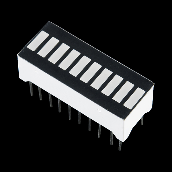
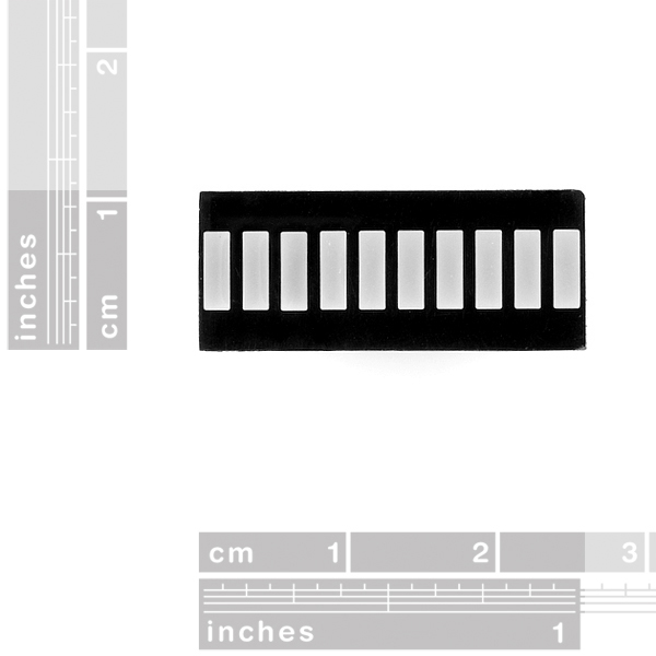
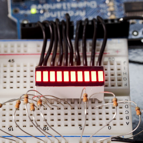
These 10 segment bar graph LEDs have many uses. With a compact footprint, simple hookup, they are easy for prototyping or finished products. Essentially, they are 10 individual red LEDs housed together, each with an individual anode and cathode connection.
We also carry these in yellow, blue, and green.
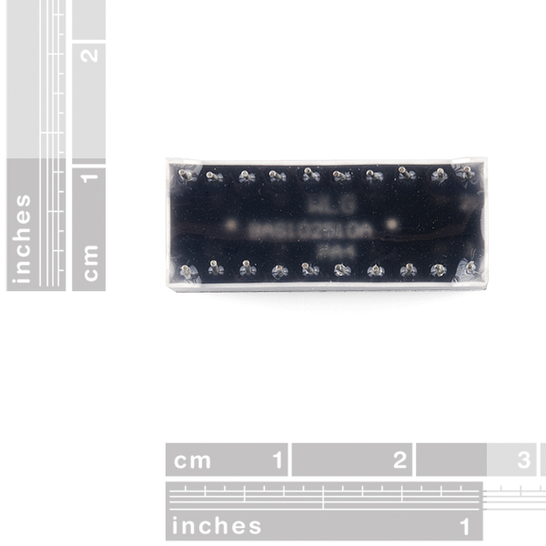
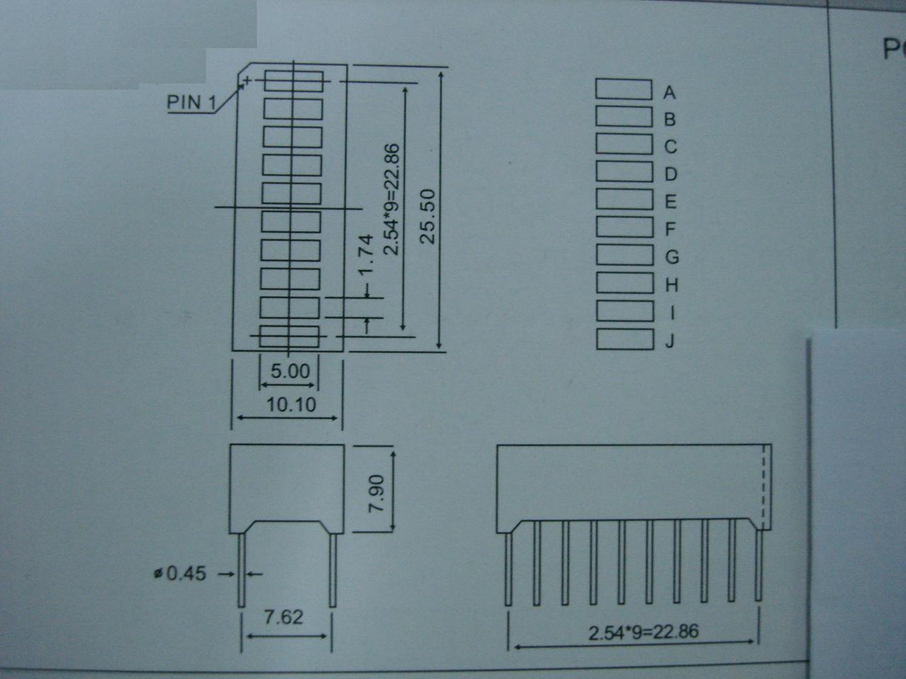
Note: The pinout on these bar graphs may vary from what is listed on the datasheet. Rotating the device 180 degrees will correct the change making pin 11 the first pin in line. We have contacted our supplier to correct this mistake in the future.
10 Segment LED Bar Graph - Red Product Help and Resources
Dot/Bar Display Driver Hookup Guide
January 16, 2014
How to hook up the LM3914 or LM3916 to drive a 10-LED display with a lone analog signal.
Sound Detector Hookup Guide
February 27, 2014
The Sound Detector is a microphone with a binary output. This guide explains how it works and how you can use it in your projects.
Core Skill: Electrical Prototyping
If it requires power, you need to know how much, what all the pins do, and how to hook it up. You may need to reference datasheets, schematics, and know the ins and outs of electronics.
Skill Level: Competent - You will be required to reference a datasheet or schematic to know how to use a component. Your knowledge of a datasheet will only require basic features like power requirements, pinouts, or communications type. Also, you may need a power supply that?s greater than 12V or more than 1A worth of current.
See all skill levels
Comments
Looking for answers to technical questions?
We welcome your comments and suggestions below. However, if you are looking for solutions to technical questions please see our Technical Assistance page.
Customer Reviews
No reviews yet.

Someone tell me how to right one of these up to a mini photocell or lilypad light sensor so that it roughly measures the amount of light coming in. Is it possible?
Yes, using "if" statements from the resistance values of the photocell to light up certain led's. If the resistance = this, then turn these led's on.
Is there any documentation describing the wiring and implementation of this device? I'm curious about the resistor setup.
There are no resistors in these (so you'll need to add your own); they're just plain LEDs with the cathode on one side and the anode on the other.
Does Sparkfun have anything that is like the linked bargraphs below?
http://www.light-bo.com/products/5-Segment-Multi-colour-LED-Light-Bar-1110624.html and http://www.light-bo.com/products/Super-Bright-Green-Yellow-Red-10-Segment-LED-Light-Bar-1110710.html
Both seem like really good choices for use with something like the fuel gauge https://www.sparkfun.com/products/10617 that aren't just 1 solid color.
Nope. You could make your own with a bit of green and red plastic (filter) using the 'yellow' bar graph (more flexibility that way, too). But then again, you could just order that type of bar graph elsewhere.
would it be possible to cut one of these down to a different size? say 8 segments?
It's basically a blob of epoxy so you'd have to use a saw, but since all the LEDs are separate, it should be possible. Let us know how it works!
Is it just me or are the anode and cathode pins backwards on the datasheet? After hooking these up it appears pin 1 through 10 should be cathode (GND) and 11 through 20 anode (+V)?
When will this be back in stock?
Thank you
Any chance you will start carrying resistor packs? It would make wiring these things up a ton easier.
Yep, I had that same idea when I was using these for something. We got some and they're on their way. However, they don't sell 10 resistor bussed packs commonly, so we got 5-packs. They have 6 pins in-line and one 'common'. Two of them work well with these.
You should sell exactly this, but with resistance built-in. Would be awesome. I have having to put resistance for LED... it's a waste of breadboard.
yea resistor packs are actually a really good idea for something like this :)
This is what it looks like in action:
http://www.youtube.com/watch?v=mxIqXESz5tQ
Do you plan to make/carry an analog-to-bargraph IC? I'd love to have some of these going as analog indicators but I can't have each one eating 10 GPIO. Also, inb4 shift register.
The LM3914 and LM3915 are great analog drivers for these graphs. I'm surprised Sparkfun doesn't carry them, but you should be able to find them without too much trouble.
I've used the LM3916 with these in the past. It's very similar to the LM3914/15. They all drive 10 LEDs which is a perfect fit. Plus, no need for a uC interface, they can be completely stand-alone.
Hook up the RSSI PWM output from an xbee module through a low-pass filter, into one of these LM3916 and you have something pretty cool...
According to the datasheet, the maximum current for these devices is 20mA, or 30mA at a 10%, 10kHz square wave. It appears that you've got these connected to your 5V Arduino with 330 ohm resistors, which would give a current of 15mA (And overload the GPIO ports you've got connected, but OK). Over 10 segments, that's a lot of power dissipation! It's also very, very bright as evidenced by the glow off of the resistors and wires.
This is probably more brightness than I need, and more power than I can afford. What is the minimum current required to get an easily visible graph under indoor lighting conditions?
For anyone still interested, the red bargraph is quite readable (indoors in a brightly-lit office) with a 1K resistor at 5V, which is 3mA through the LED.
IMHO it wouldn't hurt adding "we also carry this in green, blue and yellow" to the description, linking to the respective related products (and do the same, mutatis mutandis, for the other colors) :)
Good idea. Added to both these and the alphanumeric displays.