×
SparkFun will be closed Nov. 28th and Nov. 29th in observance of Thanksgiving. Any orders qualifying for same day shipping placed after 2:00 p.m. MST on Wednesday, Nov 27th will be processed on Monday, Dec 1st. Wishing you a safe and happy holiday weekend from all of us at SparkFun!
BigTime Watch Kit
**Replacement: **KIT-11178. We've made some changes to make this kit easier for beginners. It still work the same way, though, no worries! This page is for reference only.
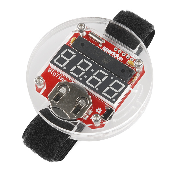
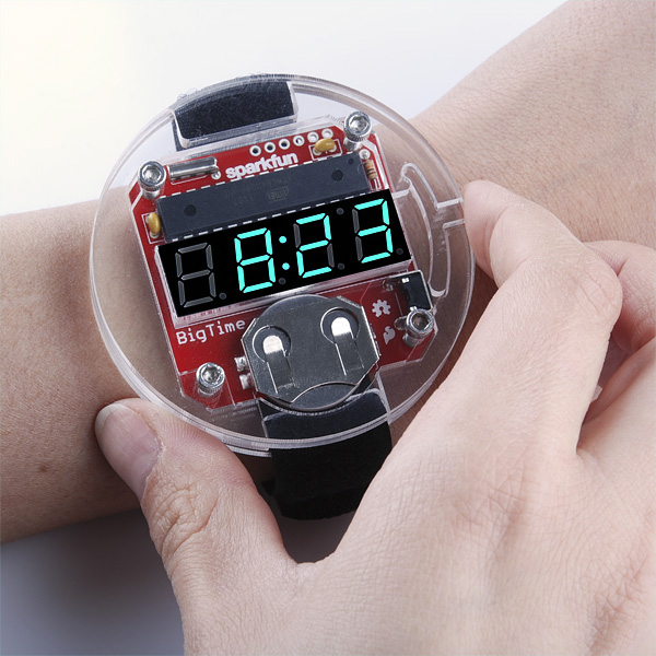
It's official, SparkFun has made the Big Time, and now you can make it too! The BigTime watch kit is a geekishly stylish digital watch with a velcro watch-band and a slick acrylic enclosure. If it seems familiar, that's because it's essentially our open-source branch from the SpikenzieLabs' Solder:Time kit. The heart of the kit is the much venerated ATMega328 using a 32kHz clock-source to keep time. To check the time, just press the button on the side of the watch and it pops up on a 4-digit 7-segment LED display. Thanks to some low-level hackery, the ATMega is running at super low power and should get an estimated 2 years of run time on a single CR2032 coin cell!
The BigTime is a through-hole kit with a low parts-count, so it makes a great project for beginning solderers. After you've finished soldering together the PCB, simply stack the acrylic pieces around it and screw them together with the included hex-head screws. Once that's done, pop in the coin-cell battery and go show off your nerd bling!
Did we mention that the watch kit is super hackable? An FTDI header is broken out to the side of the board and the watch-firmware is running on top of a bootloader! This means that all you need to do to add your own code is to open up Arduino or Wiring and select "Arduino Pro or Pro Mini 3.3V/8MHz w/ ATmega328" as your board.
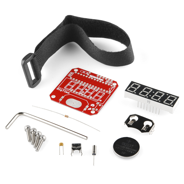
- 1 x Pre-programmed ATMega328 DIP IC
- 1 x 4-Digit 7-Segment Display
- 1 x 32kHz Crystal
- 1 x 10kOhm Resistor
- 2 x 0.1uF Capacitors
- 1 x Right Angle Tactile Button
- 1 x 20mm Coin Cell Battery Holder
- 1 x 20mm Coin Cell Battery
- 4 x 4-40 Screws
- 1 x Allen Wrench
- 1 x Velcro Watch Band
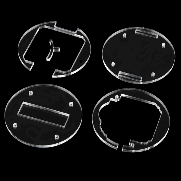
- Acrylic Enclosure Parts
- Assembly Guide
- Very hackable ATMega328-based kit with Arduino bootloader
- All through-hole components
- Estimated 2-year battery life
- Laser-cut acrylic enclosure
- Large, easy-to-read display
- Adjustable velcro watch-band
- Schematic
- Eagle Files
- Firmware (on GitHub)
- Enclosure Files (on GitHub)
- Assembly Guide
- Adventures in Low Power Land
Comments
Looking for answers to technical questions?
We welcome your comments and suggestions below. However, if you are looking for solutions to technical questions please see our Technical Assistance page.
Customer Reviews
No reviews yet.


Quick question:
is there a way to get the PCB in another color? (Please don't kill me!) I love the Sparkfun red, but it's a bit difficult to wear such red with any clothes and I'm such a geek I'll wear this proudly the rest of my life if I can!
You can send the bord files over to Batch PCB and get them to dye it a new colur for you.
I was so excited to get this for my son, but we got really disappointed in the solder iron and stand quality. The tip was impossible to keep from oxidizing. The base was so light and narrow that it tips over all of the time. But, we still had fun, just a wee bit annoyed. Does anyone have tips for caring for this iron tip that oxides on sight!
geewiz, it would be great to add Bluetooth wireless to this watch! Any possibilities?
Is it possible to use a differently colored LED display for this? It'd be nice to have the display in red.
Absolutely! This kit uses the COM-09481 ( https://www.sparkfun.com/products/9481 ), but the other displays from the series in the related products below are the same size and have the same pinouts. So you could get, for example, the COM-10931 ( https://www.sparkfun.com/products/10931 ) - which is white - and just drop a red filter in front. There's also a red display, which will always be red (the white will probably shift colors as the years go by), but the white has the advantage that if you change your mind, you can just stick a different color filter in front - or two pieces of filter so that you can make the hours one color, the minutes another, etc. The only modification you may have to make is adding a little resistor to the common pin on the display to act as a current limiter for the red/green/yellow displays (the white seems to have an incorrect Vf spec listed, see comments there) - but given how this kit works, I don't think even that would be an issue.
Didn't think about using filters. I'll consider that. Thanks!
Is there a PDF file for the enclosure? I can only find a svg file on the github web sight.
Mine is a silly question, but where can I get the velco watch band?
I have found that when I get out of my car and shock myself on the door when I close it with my watch hand that the display turns on. I don't observe any apparent damage to the operation of the watch, so my best guess is that a spark arcs from the bottom right screw to the button. Thoughts?
I figured out why (I think). In this application note from atmel regarding 32.768kHz crystals, in section 4.1 it discusses how the oscillator may stop due to a noise spike or increased capacitive load caused by proximity to a hand. I have a feeling that shock to the door increased the capacitance of your hand and caused the RTC circuitry to falsely trigger an interrupt similar to the one that the button uses to turn on the display, and this mistakenly tripped interrupt would cause the display to turn on. It is also possible that this shock may throw off the accuracy of the clock. I could be completely wrong as I am new at this.
Anyone get one and didn't work the first time you tried it? I have checked everything and it looks good. So either the atmega is bad or the crystal.
Mine didn't work. It was the surface connection on the battery case that wasn't connected. I used the Eagle files to see where all the traces are and tested continuity on everything with my DMM. That's how I found it.
I tested power to the MC fine. SFE ended up sending another MC out and it worked. What a pain to remove the MC though. We did have to add some foil under the battery to make better contact since moving the battery slightly would reset it.
Did you get a gap in the case or did you trim all the pins?
Question...You think would be easy to adapt this to be powered properly ( hacked and used in a diff situation, of course, with a proper power source)?!? Will it ahev to be at the 2 volts, same as the coin cell battery ?!?
For some reason, this watch keeps really good time for a while, and then a few hours later, it will be off by several hours. It could be that since it's pretty large, I'm hitting the button with the back of my hand without realizing it. It would be nice to have a second button on the opposite side that's used to put it into time setting mode. That also might provide a nice second input if someone is trying to use it for some purpose other than as a watch.
Just a thought.
I've discovered what has been happening to make my watch change times. The third layer of acrylic, counting from the bottom, the one that looks kind of like a big letter-C, has a slot and notch that allow the button control to move. The piece of acrylic just below the notch can move, on my watch, and when it does, it applies pressure to the button control which holds the button down. It doesn't take much pressure at all. Does this happen to anyone else?
It looks to me like I might be able to fix it by drilling a very small hole that pierces that loose piece so I can pin it in place with a small screw.
I found two errors in the documentation. First, the printed documentation calls for a 100k resistor, on page 4, but the shipped resistor is 10k. (Which turns out to be correct.) On page 6, the 4 digit display is mislabeled as a 100k resistor. :)
I would suggest reinforcing the instruction to clip leads as closely as possible and to tell the user that on the bottom piece, the holes are larger on one side than the other and be sure the side with the larger openings is the one facing up.
I'm very happy with it, so far.
I also found that the info on the capacitors is not consistent, either. It says (correctly) that they are 0.1µF on the kit list, and the graphic showing where they go, but the text for step 5 says they are 1µF, not 0.1µF
Are the I2C pins available for use off the board?
check the eagle files and schematic. not much is broken out on the watch and I don't believe the I2C is.
Are the I2C pins available for use?
I would love to win the Google+ giveaway, but I am < 18, so cannot join. I hope replying here will still count. My favorite products would be the lab coat and the hoodie. Not really electronic, but really show the Spark Fun Spirit. I also, obviously, like the Big Time Watch Kit
Wait is it using the 32khz crystal as the system oscillator and does that mean i cant just use the schematic and load the correct boot loader because you guys have configured the chip specifically to run on this mode
To put in context im building a device that would be controlling the display and needed to be very low power. So my question is, would I be able to buy the same cpu from digikey burn that arduino bootloader to the atmega328 and use the same components without having sparkfun configure the chip to use the oscillator at 32khz?
Files for the acrylic case design please? Any recommended accelerometers to trigger the time display?
Also, here are the steps I followed to put it together, with a slight variation on the part of assembling the case which made it easier for me:
<a href="http://polychronis.gr/projects/playing-with-sparkfuns-bigtime-watch-kit/">http://polychronis.gr/projects/playing-with-sparkfuns-bigtime-watch-kit/</a>
Sorry for the delay! We posted the PDF and SVG files for the laser cut parts above. The entire project is open source hardware so we'll stick a CC-SA-3.0 license on the files shortly.
Awesome watch - but next time PLEASE breakout the unused pins so that we can do fun stuff with them.
I second breaking out the unused pins. A stealthy wearable arduino would be super cool. A lower power LCD display would be good as well.
Oh man I'd be totally down for a fully programmable Arduino on my wrist.
there just wasn't enough room for this revision. maybe in the future?
There wasn't enough room because you used ginormous through-hole components everywhere. That may be a comfy norm for some people, but surface-mount really isn't that hard. You'd have plenty of room with even an easily solderable 0.8mm QFP microcontroller, an LCD screen would alleviate the power problems, and SMD components like the resistor and caps.
Unfortunately, then you'd have to call it the "NormalTime," which isn't nearly as cool a name.
yep, it's a beginners kit. and starting out, through-hole is MUCH easier...
So, perhaps a beginners kit and an advanced kit?
it's certainly possible down the road... we can look into it.
is it written in the code, so that I can keep the time on ?
There's a flag at the top of the code called 'always_on' that can be set to true if you want to keep the watch on all the time. rsp is correct - the battery won't last long so external power would be a good thing.
Hey Nate- is it possible to get just the PCB and acrylic for this? I already have the atmega, display, and pretty much everything except the battery holder.
Yes, you can change the display on-time in the code; but with the display continuously on the battery would only last for a few hours.
As a timepiece, expect the accuracy to be poor. The crystal oscillator will drift due to battery voltage and temperature changes, plus the crystal load capacitors have been omitted so it may run a little fast.
BigTime doesn't have atomic accuracy by any means but we've found it to be shockingly accurate. Atmel has done a pretty good job designing their RTC oscillator. Last I checked their app notes recommended against load caps on the 32kHz crystal on the ATmega series.