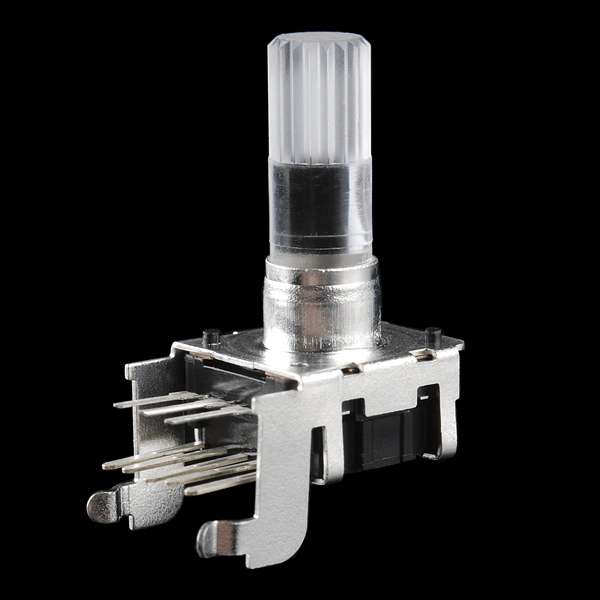
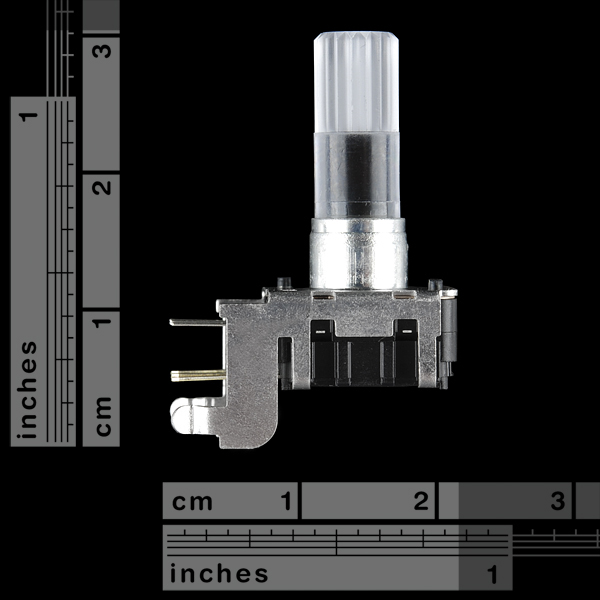
Rotary Encoder - Illuminated (RGB, right-angle)
Rotary encoders can be used similarly to potentiometers. The difference being that that an encoder has full rotation without limits (It just goes round and round). They output gray code so that you can tell how much and in which direction the encoder has been turned. They're great for navigating menu screens and things like that. This encoder mounts at a right angle so it's perfect for things like control panels and rack-mount enclosures.
This encoder is especially cool because it has a common anode RGB LED built in, as well as a push-button. Look below for the clear knob that goes with this potentiometer.
- Switch Travel: 0.5mm
- Shaft Diameter: 6.0mm
- Shaft Length: 18mm
- Right-Angle Through-Hole Mount
- 24 Pulses per Rotation
- Red/Green/Blue LED
- Pushbutton
Rotary Encoder - Illuminated (RGB, right-angle) Product Help and Resources
Core Skill: Soldering
This skill defines how difficult the soldering is on a particular product. It might be a couple simple solder joints, or require special reflow tools.
Skill Level: Noob - Some basic soldering is required, but it is limited to a just a few pins, basic through-hole soldering, and couple (if any) polarized components. A basic soldering iron is all you should need.
See all skill levels
Core Skill: Electrical Prototyping
If it requires power, you need to know how much, what all the pins do, and how to hook it up. You may need to reference datasheets, schematics, and know the ins and outs of electronics.
Skill Level: Rookie - You may be required to know a bit more about the component, such as orientation, or how to hook it up, in addition to power requirements. You will need to understand polarized components.
See all skill levels
Comments
Looking for answers to technical questions?
We welcome your comments and suggestions below. However, if you are looking for solutions to technical questions please see our Technical Assistance page.
Customer Reviews
No reviews yet.


The description says "Gray code", but this is a quadrature encoder, as shown by the datasheet and tutorials. Yes, quadrature is technically a subset of Gray code, but "Gray code encoder" implies one Gray code cycle per rotation (i.e. usable for absolute position), IMO.
It's not a problem that this is a quadrature encoder—they're easier to interface with and adequate for most applications—but I would prefer a clearer description.
ETA: From the comments on the non-right-angle version of this encoder, I learned that it's actually 96 transitions per rotation. It's 24 full quadrature cycles per rotation; 1 quadrature cycle per detent. (I guess "24 pulses per rotation" could be considered correct, if you interpret "pulses" to mean either pulses of torque resistance, not electrical pulses, or electrical pulses on just one of the quadrature pins.)
As per the data sheet the row with 3 pins seem to be 2.5mm spaced but the row with 5 pins is 2mm spaced. And the two rows are 3.1mm apart. So ignoring the 2 non-signal tabs, will the other pins fit on a bread board? Perhaps with a little bending?
There no eagle footprint for this ?
I was going to say "sure there is", but that's for the upright one. Here's a library with a single Device with the right angle package, based on SparkFun-Electromechanical.lbr/ENCODER_RGB_CA which only had the upright package. The only electrical difference is the addition of a NC pin connected to the two structural support pads, in case you want to do any grounding of them. The Document layer contains secondary package outlines. Please keep in mind that I don't have this part, and those dimensional drawings are conflicting, but the pad layout should be fine. ~~http://www.filedropper.com/com-10984~~ github:EagleWorks - COM-10984.lbr
Do you still have the footprint for this? I tried your filedropper link, but get redirected to an 'upload' screen. Thanks.
Hi there! Thanks for the heads-up. It now has a somewhat more permanent place in my (mostly empty) github repository; https://github.com/EagleWorks/eagle/blob/master/lbr/COM-10984.lbr . On that page, right-click 'Raw', and save the link :)
Something like this (right angle mount) without RGB and with built-in push button switch on the shaft would be great...
I think there is a button.