SparkX Qwiic RF - LoRa®-enabled 915MHz
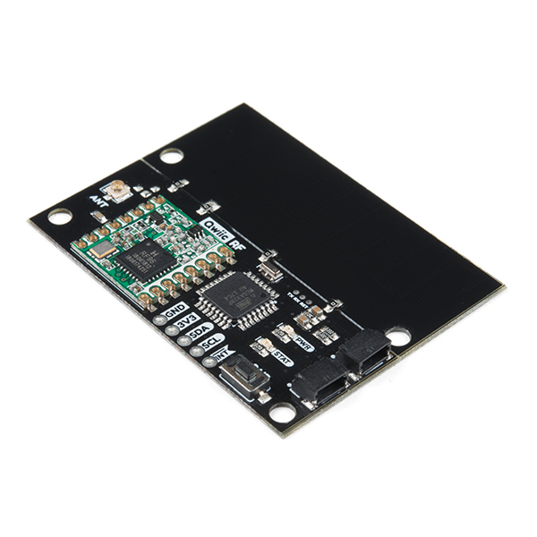
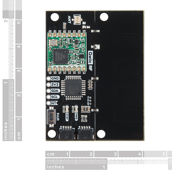
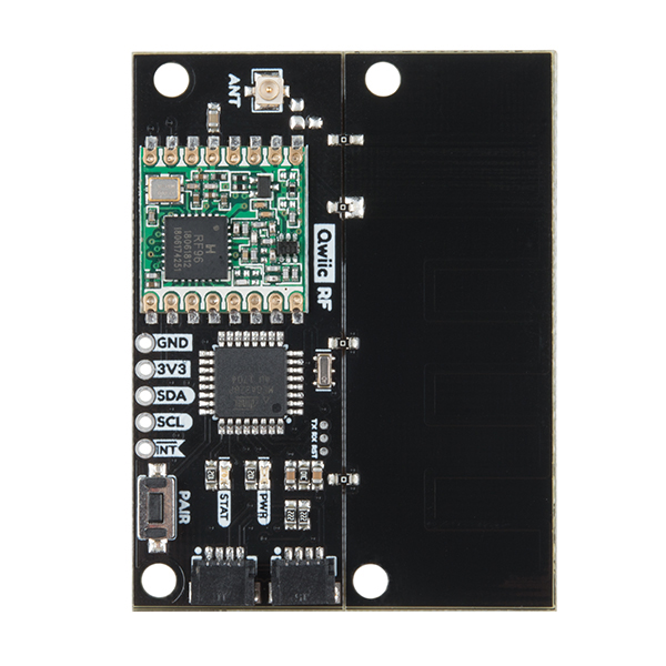
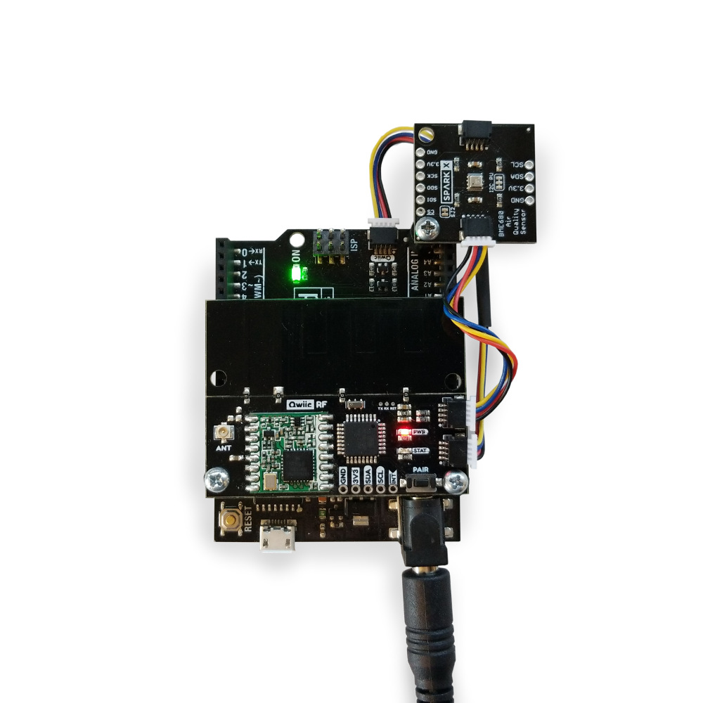
Qwiic RF is a packet radio system that's designed for sending short packets of sensor data from one Qwiic bus to another. Messages sent by one Qwiic RF are cached by the receiving Qwiic RF until they can be retrieved over the Qwiic bus. We've even written an Arduino library to do most of the work for you!
The RF Backbone of the Qwiic RF is the HopeRF RFM95W LoRa®-enabled radio module. This module is extremely long-range for its power class. Using only the attached patch antenna, we were able to send and receive packets between two of these boards up to 1.5 miles (about 2.5 km) line-of-sight in ideal conditions.
If that's not enough for you, longer distances should be achievable using high-gain directional antennas. A U.fl connector on the board can be used to connect an external antenna (after closing the appropriate jumper) and you can even snap off the patch antenna to save space if you don't need it! Accommodations are also made at the antenna feed for additional 0603-sized components to be added either in line with the signal or shunting the signal, in case you need to tune the antenna to account for hand effects or other coupling effects.
The Qwiic RF also implements a primitive pairing function for convenience. Paired radios agree on a random shared network ID and exchange randomly generated addresses. Once two radios are paired, messages can be sent between them by calling the .send() function without an address argument.
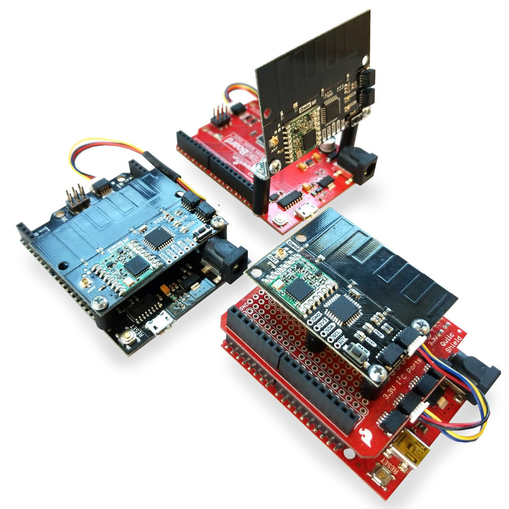
The mounting holes in the Qwiic RF have been positioned to make mounting to an Uno shaped board easy.
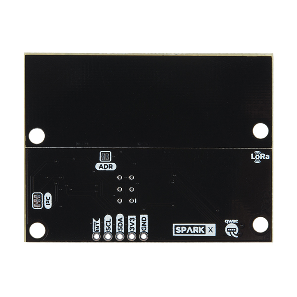
NOTE: The I2C address of the Qwiic RF - LoRa is 0x35 and is software configurable with jumper to restore defaults. A multiplexer/Mux is required to communicate to multiple Qwiic RF - LoRa sensors on a single bus. If you need to use more than one Qwiic RF - LoRa sensor consider using the Qwiic Mux Breakout.
Experimental Product: SparkX products are rapidly produced to bring you the most cutting edge technology as it becomes available. These products are tested but come with no guarantees. Live technical support is not available for SparkX products. Head on over to our forum for support or to ask a question.
- LoRa®-enabled
- Qwiic Compatible
- Range of up to 1.5 miles with integrated antenna
- U.fl connector for external antenna
- Pairing functionality
SparkX Qwiic RF - LoRa®-enabled 915MHz Product Help and Resources
Three Quick Tips About Using U.FL
December 28, 2018
Quick tips regarding how to connect, protect, and disconnect U.FL connectors.
Comments
Looking for answers to technical questions?
We welcome your comments and suggestions below. However, if you are looking for solutions to technical questions please see our Technical Assistance page.
Customer Reviews
No reviews yet.

Something I'm observing makes me think these boards are being made with the wrong crystal oscillator. When I set the reliable send timeout to X seconds and make sure there are no other clients to respond, the timeout takes 16X seconds to clear. 16 is suspiciously the same as the schematic value for the oscillator in MHz. If the boards were being produced with a 1 MHz oscillator instead, I think that would explain the behavior.
Are you referring to the crystal for the ATmega328? 16MHz is pretty standard; as in, that is what is used on the Arduino Uno and the SparkFun RedBoard.
I might be totally wrong about the reason for the problem but I am definitely observing an issue with the delay being exactly 16 times what I specify
Unfortunately, there doesn't seem to be enough information to look into the crystal as an issue. However, it does seem like you are looking for some assistance and as mentioned in the product description, "Live technical support is not available for SparkX products. (But, you can) head on over to our forum for support or to ask a question."