Qwiic AS3935 Lightning Detector
This board has gone red! Checkout the new version here.
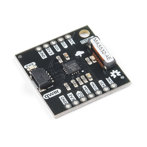
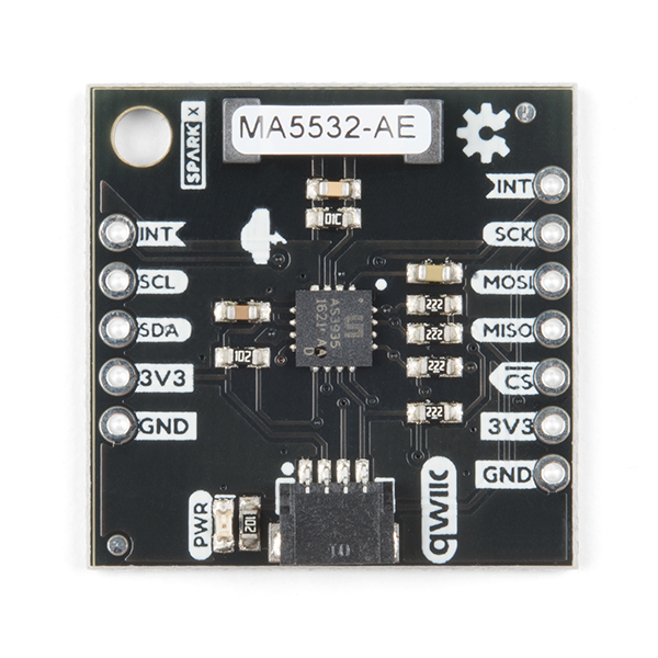
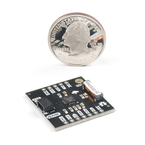
The AS3935 Franklin Lightning Detector gives you lightning detection for your next weather project. This sensor is capable of detecting lightning up to 40 km away with an accuracy of 1km to the storm front! On the product is a sensitive antenna tuned to pick up lightning events in the 500kHz band. When sensing an event the AS3935 utilizes an interrupt to the interrupt pin, distinguishes between false and real lightning events, and has a number of features to help calibrate lightning detection. For example, there are settings for detecting from indoors or detecting from outdoors, settings to change the threshold for false events, and settings to be alerted only after a certain number of lightning strikes to name a few. We've also written an Arduino Library to get you prepared for that upcoming storm! Check under the documents tab under Library and Example Sketches.
The product is capable of communicating over SPI or I2C and sports a Qwiic connector for fast implementation without the need for soldering.
Experimental Product: SparkX products are rapidly produced to bring you the most cutting edge technology as it becomes available. These products are tested but come with no guarantees. Live technical support is not available for SparkX products. Head on over to our forum for support or to ask a question.
- Lightning Sensing
- 40 km Range with accuracy of 1km in 14 steps
- Features
- Programmable Detection Levels
- Distance to storm estimation
- "Disturber" (false event) rejection algorithm
- Indoor and Outdoor Settings
- SPI and I2C Interfaces
- Qwiic Enabled
- Operating Range
- Supply Voltage: 2.4V - 5.5V
Qwiic AS3935 Lightning Detector Product Help and Resources
SparkFun AS3935 Lightning Detector Hookup Guide (v20)
July 25, 2019
Are you worried about the looming clouds in the distance, how far away is that storm exactly? Add lightning detection with the AS3935 to your next weather station or your next bike ride!
Comments
Looking for answers to technical questions?
We welcome your comments and suggestions below. However, if you are looking for solutions to technical questions please see our Technical Assistance page.
Customer Reviews
4.4 out of 5
Based on 5 ratings:
2 of 2 found this helpful:
It's really Qwiic + 1 for the Interrupt line, but it runs great
tl;dr This board has a couple of small quirks, but works very well. Don't change the default i2C address, and plan on heating up your soldering iron.
There are two small issues with the breakout board to note.
1) It requires an interrupt line to be used along with the Qwiic connector, so it's not pure Qwiic. (You probably will need to solder a pin for the interrupt line, just plugging in a qwiic cable is not sufficient to run this breakout board.)
2) The I2C address is in the reserved range (below 0x07). The default address 0x03 is probably fine, since 0x03 and 0x02 addresses are reserved for CBUS which is now obsolete and no longer in use. Address options 0x00 and 0x01 could cause problems.
The address 0x00 is reserved for general call, and used to send a command to all i2c devices, so that would be a bad choice. The byte 0x01 is also reserved as a start byte for manual i2c transmission and would probably be a bad choice.
https://www.i2c-bus.org/addressing/
I read the spec sheet for the chip and these issues actually spring from the architecture of the chip itself, not from Sparkfun's design of the breakout board.
Those two quibbles aside, this detector works fine and is a good package.
AS3935 breakout boards are notoriously finicky and I've run across some painful design issues with AS3935 breakout boards from other vendors. (AS3935's can ring like the buzzer on a discount cat house, if the antenna design isn't done right.)
This design is stable. Mine doesn't drift into noise oscillations, after a long period of use. That alone is worth 5 stars.
Unique sensor
Great fun little sensor. I set mine up to ring a bell when lightning is near
That's a great project idea! Thank you for your review. :-)
good board, sparsely documented
(I live in an area that doesn't get many thunderstorms, so I am still waiting to see if this actually does the detecting part of the detector.)
The board itself is OK, I think. The price is good for an AS3935 breakout board, which are generally hard to find in the first place. Because everybody's price is kind of high compared to other sensors you might buy, I suspect the AS3935 chip itself is quite expensive.
Like all AS3935 breakouts, there is an antenna on the board (it's the part labelled MA5532-AE). The AS3935 has a bank of 16 internal tuning capacitors. You have to calibrate the antenna circuit with them to resonate as near as possible to 500kHz. The chip maker says if you don't get within 3.5%, it won't work. I was a little concerned that only capacitor tunings 14 and 15 were in range. I don't know if that's typical for these boards.
I only know about the antenna tuning from looking at the full AS3935 datasheet and reading discussions of other AS3935 breakout boards. It's mentioned in the comments of the SparkFun software library, but neither of the example sketches does the antenna tuning. That software library, by the way, has some serious bugs in it (and various minor annoyances). I started working my way through it to be able to do the calibration, but I finally gave up and used a different AS3935 library to find the correct antenna tuning.
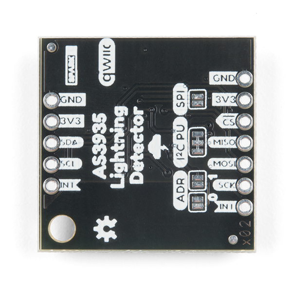
Those other libraries happened to all use SPI, so I had to put a solder bridge on the provided pads on the back of the board to switch to the SPI interface. Speaking of that, you will want to have a look at the schematic file (provided as a PDF) to see what those jumpers are all about. I didn't find them documented elsewhere, but the schematic page is very clear.
To recap, this is a SparkX board, so the quality of the supporting material is not what you might normally expect from SparkFun. They tell you that, so it's completely fair. You should just have your eyes open that you need to understand the AS3935 chip itself or you are likely to have disappointing results.
Good Addition to the Quiic Line
Have yet to catch a storm, but after the latest AS3935 library update, the board is communicating great using the Qwiic system. Seems simple enough to use. Storms should be rolling over pretty soon once August rolls in.
Works really well with Cacti and MRTG on Pi3
This is the second one I bought and it works better than the first. The first was a red board with Qwiic this one is dark gray. I'm using it with the demo python code and library to generate a log of lighting strikes and logging that to a file in memory, then grep wc -c to count the number of strikes on the Cacti scheduler as a counter. It seems accurate. This is located in Missouri where a lot of thunderstorms roll through this time of the year. The code really needs that extra Interrupt connection to GPIO17 or it doesn't work at all. i2C does the programming and fetches the distance info, but the INT causes the code to go get it. -- I didn't want to solder anything, so used a Wirewrap tool to attach a 32 gauge wire from a small number of push pin IDC connectors on the lightning board and connected the INT to the GPIO17. Perfect connection. Wirewrap tools are "the best" when working with IDC pins and Raspberry Pi

On your other AS3935 based decide you say that while I2C is on the board only SPI is supported due to apparently occasional issues and bad support by the manufacturer of the chip, but make no such disclaimer for this product which I assume would have the same issue. Has that been resolved or does Sparkfun also only support SPI for this device?
It has the same issue.
There is a CircuitPython library now available for the Qwiic AS3935 Lightning Detector and the Raspberry Pi. The source code, examples, installation information and documentation are available on GitHub.
https://github.com/fourstix/Sparkfun_CircuitPython_QwiicAS3935
Is there another run of these planned, or are they gone for good? I just discovered this and would love to get one!
I just spoke with one or our interns, and she's on the case! I can't give any specific times as parts need to be ordered and build times vary. TLDR, they will be coming back in stock.
It just needs a 'blinkin' light/LED and optional buzzer to be perfect.
Nice! Too bad Ben Franklin didn't have one of these back in his day.
He died 100 years too early =/ https://en.wikipedia.org/wiki/Alexander_Stepanovich_Popov