Header Board for LPC2468
Replacement: None. There is no direct replacement for this board. This page is for reference only.
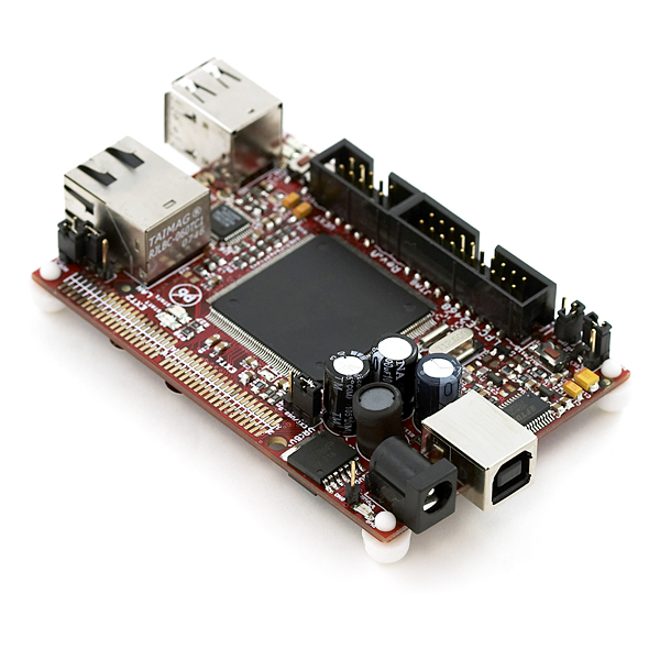
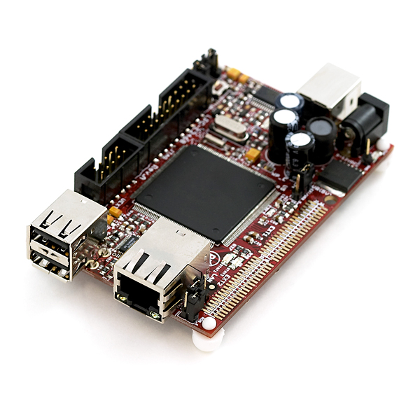
Development board for the ARM7 LPC2468.
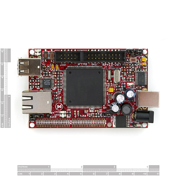
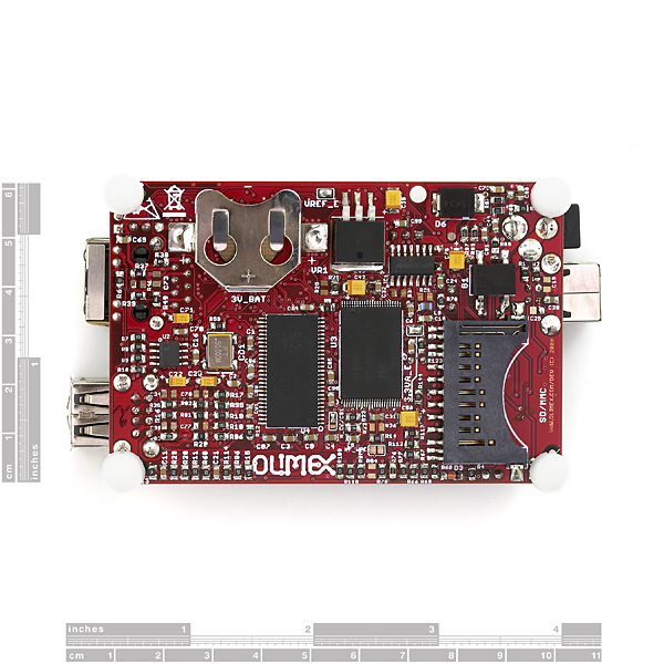
LPC2468 * 16MB SDRAM * 128 MB NAN Flash * Standard JTAG connector with ARM 2x10 pin layout for programming/debugging with ARM-JTAG * Ethernet 100MBit * 2x USB hosts * USB-to-RS232 converter device connected to LPC2468 UART * SD/MMC card connector * UEXT connector with I2C, SPI, RS232 and power supply for connecting add-on modules like RF link, MP3, etc available from Olimex * Trimpot connected to ADC * RESET circuit with external control of Philips ISP utility via RS232 port * Two USER button * RESET Button * Two on board voltage regulators 3V and 5V with up to 800mA current * Extension port connector for many of microcontrollers pins * Single power supply: External power supply, USB or JTAG connector * Battery holder and connector for the RTC * Power supply led * FR-4, 1.5 mm, red soldermask, component print
- MCU:
- 90x60mm (3.54 x 2.36")
Comments
Looking for answers to technical questions?
We welcome your comments and suggestions below. However, if you are looking for solutions to technical questions please see our Technical Assistance page.
Customer Reviews
No reviews yet.


JB: Any thoughts on what I should use for a bus connector? I assume I need solder something to the pads along the edge.
I agree those pads look hideously tiny. Can anyone offer any info on connectors for this thing? I really want to get it but those pads are holding me back
Thanks
James
Hi,
I bought this development board and bus connector is very easy to solder. It is a version with 1.27mm distance between pads. I got two pieces of this http://cz.farnell.com/jsp/search/productdetail.jsp?SKU=1667674 for development board and two of this http://cz.farnell.com/jsp/search/productdetail.jsp?SKU=1667766 for my custom board.
Any thoughts on what I should use for a bus connector? I assume I need solder something to the pads along the edge.