- Home
- Product Categories
- Components
- Transformer Modem 600:600 Ohm (PTH)

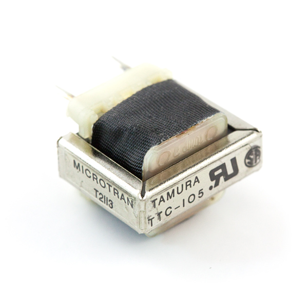
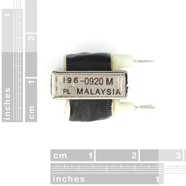
Transformer Modem 600:600 Ohm (PTH)
Replacement: None. It's time for this product to step aside and make room for more cool stuff. This page is for reference only.
This is a simple, through-hole transformer. Both primary and secondary windings have a 600Ω impedance rating. As the turns ratio is 1:1, this transformer is geared towards isolation rather than voltage transformation.
We use this transformer in our Geiger counter kit, but it has many other uses such as decoupling and isolating.
Note: Not a robot in disguise.
Comments
Looking for answers to technical questions?
We welcome your comments and suggestions below. However, if you are looking for solutions to technical questions please see our Technical Assistance page.
Customer Reviews
No reviews yet.
"Note: Not a robot in disguise."
lol
When will this be available again?
never!
I have been trying to use this as an isolation transformer to connect the audio from a toy robot to a Class-D amp line input (To be able to amplify the robot sounds to a much higher volume).
It sounds great, but I just had my second audio synth board on the robot fail. Each time it worked fine until suddenly dying. Now that I think about it I wounder if it is not an appropriate use for this transformer. If the little toy audio circuit was intended to drive an 8-Ohm voice coil and now it is driving a 600Ohm winding, could that have overloaded and damaged the audio driver?
I have since found an alternative bridge circuit that uses a simple 10:1 voltage divider to feed the amp input a voltage closer to what it is designed for. Could this be a better solution?
Any help is much appreciated.
Rob
What's the role of this transformer in the geiger kit ?
It's operating as a Flyback Transformer
With no air gap, no ferrite and no feedback ?
And the ratio is 1:1. I sure don't understand.
Yeah on the surface you'd think a 1:1 xformer wouldn't raise the voltage much, I think this is based on the priciple that an energised coil can produce a very large reverse voltage spike when the voltage across the coil is removed suddenly (hence why sometimes you need a reverse protection diode across relay coils to suppress the spike produced by the reverse EMF). It is this spike that then induces an equivalently high voltage in the secondary , which I imagine is kind of redundant in this particular circuit, you could just use an inductor instead of the xformer and take the output from the D1/Q1 junction into the voltage doubler. I also have some doubts that the voltage doubler is correctly implemented, normally I would expect D2 removed, ground connection moved to D3/C4 junction and C4/C7 merged into just one cap, but hey, if it works, who am I to argue ... :)
Don't you mean 'Modem Transformer', as in the type of transformer used in modems?
These are used to couple the modem to the phone line in order to meet the isolation and impedance requirements of the telephone system.