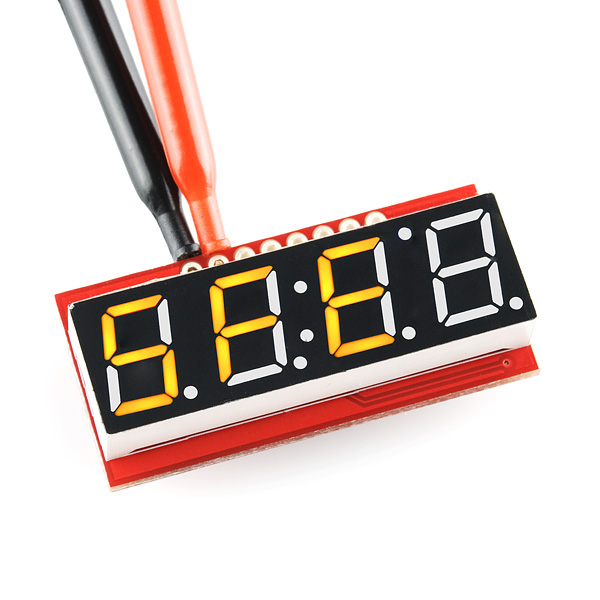
7-Segment Serial Display - Yellow
Replacement:COM-11443. We've overhauled this board adding I2C functionality, and Arduino bootloader and mounting holes! This page is for reference only.
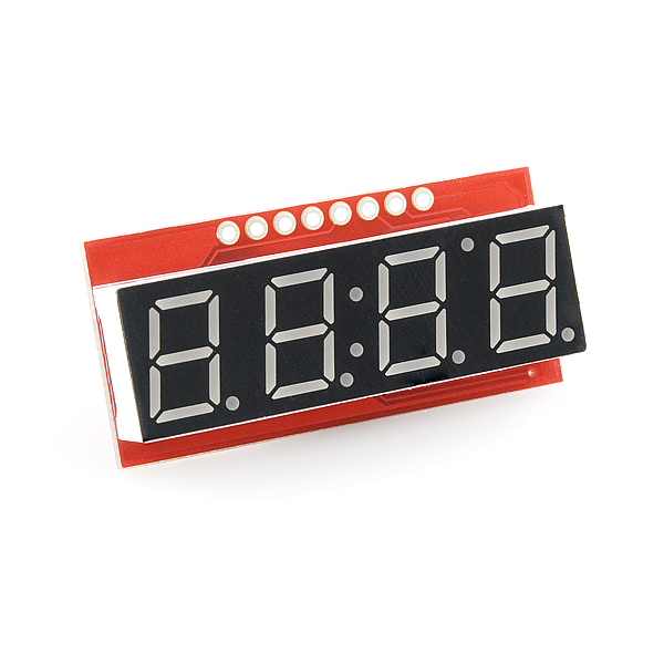
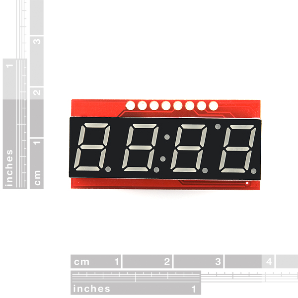
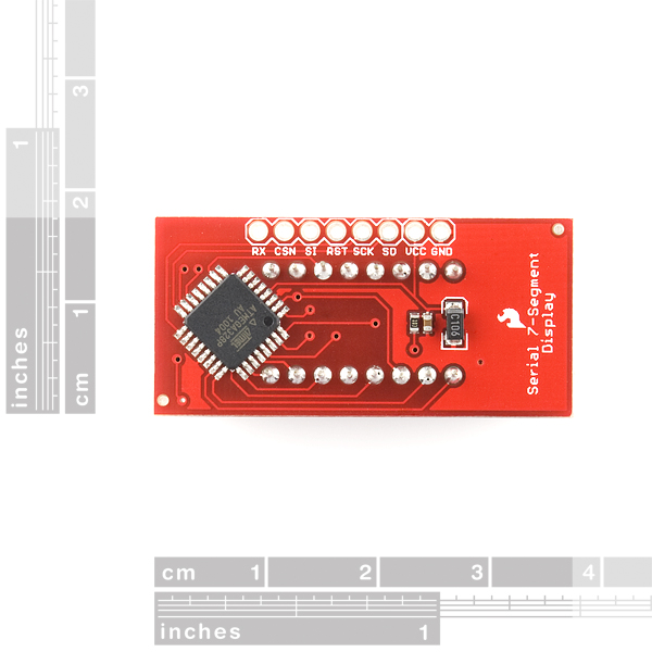
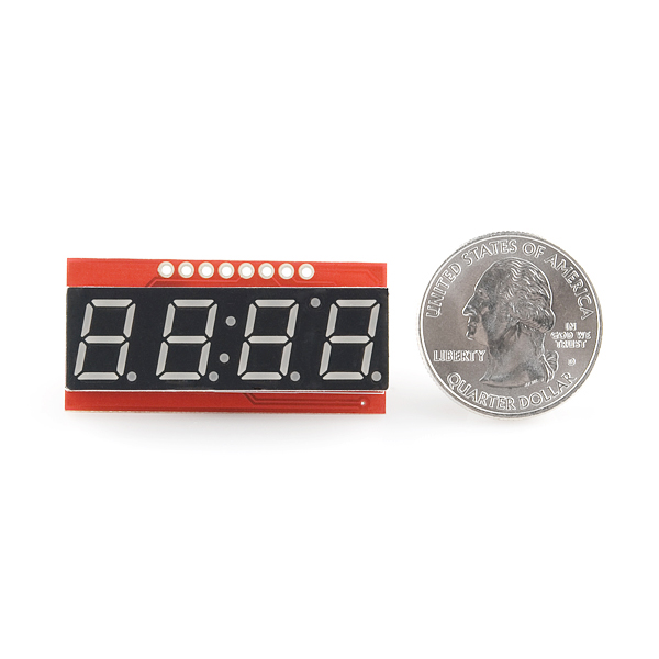
The 7-Segment Serial Display turns the thirteen pins necessary to control a 4-digit seven segment display into just one or three. The display will give you full control of all digits, decimal points, the colon and the apostrophe. At the heart of the display is an ATMega328 which controls all the serial communications and the 4-digit 7-segment display through an easy to use API.
The Serial 7-Segment Display can be controlled in one of two ways: (1) serial TTL communication or (2) SPI serial communication. Regardless of which method you use to communicate with the display, the display is controlled with 4-byte packets and special 2-byte commands.
*New for version 2: *The input and power pins have been moved to the top of the display, allowing you to place the displays side-by-side. Additional characters have been added, including the "-". A reset display command and single character control have also been added. See the new user's manual below for detailed information about all of the new features!
- 4-digit yellow alpha-numeric display with serial (1 pin) or SPI interface (3 pins)
- Display numbers, most letters, and a few special characters
- Individual control of decimal points, apostrophe, and colon
- Selectable baud rate (2400 to 57600 bps)
- Selectable brightness
- Baud rate and brightness values retained in non-volatile memory
- Individual segment control for each digit
- User's Manual
- Schematic
- Source Code (ATmega328)
- Eagle Files
Comments
Looking for answers to technical questions?
We welcome your comments and suggestions below. However, if you are looking for solutions to technical questions please see our Technical Assistance page.
Customer Reviews
No reviews yet.

I agree that the firmware is poor. I didn't try to use SPI so I don't say anything about that, with serial this works ok. <br />
<br />
But the code looks ugly. And because there is no resistors, the only thing limiting the current LEDs get is 168's ability to source current, causing digit brightness to vary. Eg segments on digit "1" (2 LEDs lit) are much brighter than on digit "8" (7 LEDs).<br />
<br />
I wrote a firmware of my own that fixes this by altering duty cycle, to compensate this.
Could you make your firmware available somewhere for download? I'd be very interested to see how you worked tihs into the existing code.
Baud rate stuck on 9600. I can set other parameters such as brightness, but no luck with baud rate. Are there any new suggestions? I am trying to get to baud rate of 38400 for use with atlas pH stamp.
Is there a recommended bezel or method for mounting this in a panel?
Just finish a library for this display: https://www.dropbox.com/s/ssvydwuf3js3cb5/Serial7.zip It has a lot of features and works great on the Arduino UNO. Also supports the ATtiny45 & ATtiny85 (except floating point math).
FYI -- got this display working with Maple arm (arduino-like) board in serial mode using UART Tx (Serial1) and with SPI at the slowest SPI frequency (140 kHz) and also works at 281KHz
Bildr has a page on this product, that's usually the #1 link I'm looking for in the "Documents" section: http://wiki.bildr.org/index.php/7-Segment_Serial_Display
Very much useless.
I've been trying for two days to decipher the protocol as described in the user manual and all I get is random segments turning on and off.
I'm now convinced the manual was written in chinese, then translated by germans into english.
My application is netduino, connected to the display by serial interface. My test code writes 32 zeroes to the serial port (9600/n/8/1) and then just blinks the led in an endless loop. Every time I reset the device a different set of segments light up. I tried varying the port settings to no effect, tried sending reset commands - nothing helped so far.
contact tech support. techsupport@sparkfun.com. these should be pretty easy to use, especially over serial. check with them and see what they say.
Your tech support is nowhere to be found.
I did, however, figure out the problem. It was in the chinese to english translation done by germans...
Default baud rate in the manual is listed as 9600 but the actual default baud rate is 2400. As a result if you trust the manual you end up seeing random output as there's a stop bit and even sending all 0s will result in random readings by the receiving end.
tech support was nowhere to be found? They're across the hall from me, and they are all typing away furiously at their computers, trust me.
glad you got it fixed. you might have inadvertently sent a command that changed the baud rate.
pro-tip: if you have the rx connected when uploading code to the arduino, it can send all sorts of garbage and reset all sorts of things on the display. this is VERY common with a lot of our serial LCDs.
It would've been nice to mention that in the documentation.
It's also a problem that once the baud rate is set it's kept in non-volatile memory, so power-cycling doesn't reset it to 9600 and there's not signal (as in separate wire) that would cause that baud rate to be reset. There's a command to reset it but when you don't already know the rate then sending a command is not only useless (there's no feedback) but also there's no way of knowing what did the display actually read in place of what you wrote on the line.
The end result is that I can have the patience to troubleshoot one unit but I can't buy 500 pieces to make a batch of my devices, I still have to look elsewhere and will still have to spend a whole new effort to switch to another display.. Which makes this device useless, but I already pointed that out.
Well, the whole problem with using something that's serial is that as soon as you program your arduino (and the device is connected via serial), it gets all the code too, so it can reprogram the module, to no fault of the module. it just thinks it's seeing serial commands.
this is not something that is inherent to the product, but to the nature of programming an arduino with other stuff connected to the serial bus.
I made a few modifications to the firmware on my displays.
For one thing, I just hard-coded the baud rate, and removed the support for changing it. I also disabled SPI, since I'm not using it and it can be susceptible to noise. Lastly I disabled the code which saves brightness changes to the EEPROM. I control the display's brightness using the output from an ambient light sensor, and didn't want to wear out the EEPROM prematurely due to changing the brightness up to a few times a second.
With these modifications, I find the displays much harder to confuse. It's a bit of a pain to hook them up to a programmer though.
Awesome!!!!!!!!!!! Thank you :D God thanks you lol What a pain.You made me realize what was going on. This should HELP EVERYONE! using it with an arduino. When I first hooked it up it would only work at 2400. Nothing else, either jibberish or 0000's. Then I changed the baud rate in "void loop" by using:
mySerialPort.print(B01111111,BYTE);
mySerialPort.print(B00000100,BYTE);
which sets it to 19200. After that 0000's, and I was completely unable to change it back. Ive tried every baud rate over and over again. Then from reading what Member257427 said about the german chinese blabla it was originally set to 2400. BING! lightbulb. I realized I had to set in my case mySerialPort.begin(2400); to 19200. Dah! You have to reset your mySerialPort.begin(xxxx); to whatever you set it from inside the program. IDK might be a stupid answer but it seems many people are having a problem very similar to mine, and I read nothing that sais this.
SO to set this to 9600 baud rate in arduino using rx/tx fallow this.
Write this inside of void setup()
mySerialPort.begin(2400);"
Write this inside of void loop()
mySerialPort.print(B01111111,BYTE);
delay(100);
mySerialPort.print(B00000010,BYTE);
run it.
Then Delete:
mySerialPort.print(B01111111,BYTE);
delay(100);
mySerialPort.print(B00000010,BYTE);
Change: mySerialPort.begin(2400); to mySerialPort.begin(9600);
Run it, it works. These displays rock.
Also add mySerialPort.print("v"); before any new prints. This will keep the cursor in check. Or just write some code to do it every time before any new prints.
If you changed the baud rate inside of void loop(); and dont remember or know what you changed it to. You are going to have to go through trial and error.
Mose likely you have changed it to either:
2400, 4800, 9600, 14400, or 19200. Start from lowest. So do this.
in void setup()
mySerialPort.begin(2400);
in void loop()
mySerialPort.print(B01111111,BYTE);
delay(100);
mySerialPort.print(B00000000,BYTE);
delay(100);
mySerialPort.print("YESS");
run it.
if that doesn't work. Then change to mySerialPort.begin(4800);
also change the
mySerialPort.print(B00000000,BYTE);
to
mySerialPort.print(B00000001,BYTE); so on and so forth.
If you don't understand their data byte value:
B00000000,BYTE = 2400
B00000001,BYTE = 4800
B00000010,BYTE = 9600
B00000011,BYTE = 14400
B00000100,BYTE = 19200
Now once you see "YESS" printed thats what baud rate you originally set it to. :)
After numerous attempts to get this to work I have given up and thrown the board away. A total waste of $13
Did you try contacting tech support at all?
After reading Alan Burlison's blog about his attempt to get help from tech support I figured it was a lost cause.
It might have been worth at least investigating. We have thousands of customers and basing your opinion of our tech support department on one person's experience isn't fair to us.
If you let them know what specific problems you were having, they may be able to help you and we most likely would have gladly sent you a new board if the other was defective.
Sorry for your experience, but next time, at least give us a chance to help before abandoning hope.
Like!
I adjusted the brightness via the subscribed command structure. After that the display only flickers. Any ideas?
The original datasheet says the SPI interface would run at 2MHz whereas it will only do 250KHz at best - and even then it won't ever be 100% reliable. The firmware is absolutely shocking, and (amongst other problems) the SPI ISR overruns. See http://bleaklow.com/2010/08/28/sparkfun_are_less_than_electrifying.html for the sorry details. My advice - avoid this product.
While Alan raises some valid concerns, I think we should give SparkFun some credit for sharing their firmware code. It's easy to pick apart SparkFun's design and code when they give you easy access to it, but most manufacturers won't do the same, so you have no idea what the quality of code is in their products.
That said, I will admit SparkFun doesn't always produce the highest of quality products. However, their market is the hobbyist who can't afford products with rigorous QA. As a compromise, they make it easy to fix or improve by providing easy access to schematics, layouts, and source code. If a customer still isn't happy, they are always generous with shipping replacements or offering refunds.